


In the process of translating and putting online Savinov and Luskin’s classic work The Vibration Method of Driving Piles and Its Use in Construction, we come upon what to people in the industry now probably find as a surprise: the earliest units (such as the BT-5 which was used on the Gorky project in 1949) didn’t have a suspension. A diagram of such a driver is shown on the right.
Although they certainly are simple, the disadvantages of such a machine include the following:
- It is difficult to extract piles with such a machine because, in the tension of the pulling cable, the vibrations are directly translated to the crane.
- The addition of weights in the vibrating portion of the system (the item 4 on the diagram at the right) degraded the performance of the machine, as amplitude, peak velocity and peak acceleration all decrease with an increase in weight while both eccentric moment and rotational velocity are held constant.
- The electric motor vibrated along with the exciter and the pile. This shortened the life of these motors. The Russians went on to improve the quality of these motors and even adapted them for impact-vibration hammers, where the deceleration during impact typically ranged around 150 g’s. With American hydraulic vibratory units, the durability has been for the most part resolved, although careful selection of the specific motor and proper mounting are essential for success.

The year after the successful test of the BT-5, Savinov and Luskin proposed a vibrator with a suspension. A diagram of this is shown at the left. As you can see, the weights used to increase the downward force of the vibrator were now above the vibrator springs, which meant that they produced what was basically a static surcharge on the unit. How static is was depends upon how it is configured, and the relationship between the static weight above the springs and the stiffness of the springs themselves.
The first one of these machines was the VPP-1, shown below.


It is easy to see the bias weight stacked on the suspension, with the springs groaning under the weight. It is also easy to see the motor as a part of the suspension; a V-belt arrangement transmits power from the motor to the gearbox, allowing for relative movement between the gearbox and the suspension. Such an arrangement persisted in Russian machines, as can be seen in the machine Vulcan representatives saw in Leningrad in 1988 and can be seen at the post Vibro-Engineering and the Technology of Piling and Boring Work.
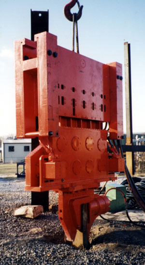
Most American machines have some kind of “box” around the springs, which are usually rubber shear fenders adopted from the marine industry. Such an arrangement can be seen at the right. In this case you can see the little dots on the suspension at the top; those are the hex heads for the bolts that affix one plate of the shear fenders to the suspension. The other plate is affixed to the shear fender mounting bracket on the inside, which in turn is connected to the gearbox.
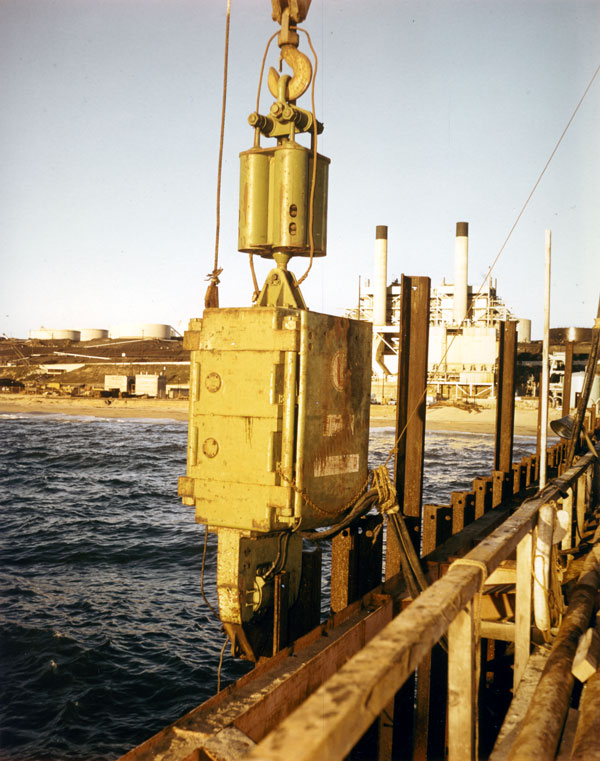
The different shape of the suspension means that the bias weights are different. The simplest way is to hang them off of the side, as is shown at the left, in this case on the Foster 4200 vibratory driver that Vulcan “private labelled” for Foster in the 1990’s.
Getting back to the Russians, they did extensive theoretical work on all aspects of the suspension design. That can be broken down into three parts:
- The relationship between the spring and the mass of the suspension, which determines the natural frequency of the suspension and thus its ability to dampen vibrations from the hammer operating at its normal frequency. We will deal with this subject below.
- The effect of bias weights on the drivability of the vibratory driver. The Russians, and this can be confirmed by anyone experienced with vibratory drivers, discovered that additional suspension weight (bias weights) can improve this drivability. How much improvement–and whether it’s worth the additional weight and load on the crane to pick it up–depends on the situation. Some of the theoretical work on this can be seen in Immersion and Extraction by Longitudinal Oscillations. The model developed in this post was brought back to life and more recently studied in the paper Reconstructing a Soviet-Era Plastic Model to Predict Vibratory Pile Driving Performance.
- The effect on the crane during stopping and starting, when the vibratory hammer is not operating at normal frequency. Even with a suspension the Russians–like everyone else–found that some vibrations were transmitted, and they did some extensive research into the problem, some of which are detailed in Means of Protection Against Vibrations of Load Lifting Devices Working With Vibration Exciters. At the start are some of our comments on their work relative to Vulcan’s experience with this topic.
One thing that needs to be noted is that today there are many relatively small, aftermarket devices to dampen the vibrations to the crane boom. Although they claim novelty they, like so many things in this business, are not new. The Uraga machine, which Vulcan marketed, was one of the most innovative Japanese vibratory drivers, and sported something like this just under the crane hook, as is shown below.
Credit should go to Tünkers for installing this on their own vibratory hammer using a rubber construction. One advantage of rubber is that it has internal damping which enhances the damping effect, as opposed to coil springs.
Going back to the first point, the Russians and Vulcan (or more accurately post-Vulcan) took a different approach regarding how to model the suspension.
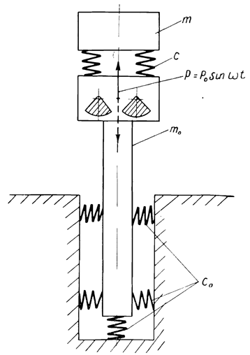
The Russians constructed a model such as is shown on the right. They modelled the soil as springs, as was the case with the suspension springs. The main disadvantage of using springs to model the soil is that the whole idea of pile driving–impact or vibratory–is to move the pile relative to the soil, which means that there is plastic deformation somewhere in the system. The elastic springs cannot replicate this effect.
Another problem, however, is that the system shown is a two-degree of freedom (with two sets of masses and springs) system. This is the same kind of system as shown in Concrete Pile Head Response to Impact, and it adds to the mathematical complexity of the system. The Russians managed, using clever assumptions, to get around this problem and consider it as a single-degree of freedom system, resulting in damping curves such as are shown below.
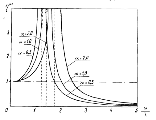
The curves show the ratio between the suspension amplitude and the amplitude of the exciter case, designated by 


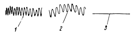
Obviously the “flatline” of Line 3 is what you’re looking for. From a theoretical standpoint, such a flatline is impossible. This leads us to a gap in the Russians’ presentation: what is an acceptable reduced amplitude/frequency ratio 
This problem was worked on at Vulcan in its last years, but it wasn’t until 2006 that a formal presentation of the results took place in Development of a Parameter Selection Method for Vibratory Pile Driver Design with Hammer Suspension. Based on experience, it was determined–and in general Vulcan drivers were designed to the criterion–that 


The model that was chosen for this analysis, however, was different than the one chosen by the Russians, and can be seen on the right. By changing the interaction between the exciter/pile and the soil from springs to a damper, it brought it more into line with the model proposed by Barkan and used by equipment designers and manufacturers. (An explanation of the two models developed early in the Russians’ program can be found in our post D.D. Barkan’s BT-5 and the Vulcan 400.) Also, by eliminating the soil spring, it simplified the system, although examination of Development of a Parameter Selection Method for Vibratory Pile Driver Design with Hammer Suspension will show the mathematics are still challenging.
This leads us to our last topic: how do these two models differ in their estimate of the effect of the suspension on driving? Neither of them is entirely satisfactory in their replication of the system. We will start with Suspended Vibratory Hammers:
This shows that if an elastic connection is introduced between the vibrator and the additional load, with an appropriate choice of its rigidity, the intensity of the pile vibrations increases with increasing load, and does not decrease, as is the case in the simplest type vibrator. Thus, by attaching an additional load through the springs, we simultaneously increase the weight of the entire system and the intensity of the pile vibrations, which will contribute to the most efficient immersion of the latter.
And then from Development of a Parameter Selection Method for Vibratory Pile Driver Design with Hammer Suspension:
The most straightforward explanation is that the mass of the suspension interacts dynamically with the exciter in such a way that the amplitude of the exciter (and by extension its power requirements) are augmented. Put another way, the suspension acts as a kind of “dynamic backstop” that focuses the energy of the system downward. This role is a supplement to the obvious one, i.e., adding static down crowding force to overcome the soil resistance and allow the pile to drop by its own weight.
Although the models are different, both predict the benefits of a suspension (with its static weight, augmented by bias weights) on vibratory pile driving.

