
1 Overview
The development of impact-vibration equipment is both an outgrowth of and parallel to the industrial application of the vibration method for driving various objects into the soil, which began in the USSR in 1940. This served as the beginning of comprehensive studies on their exploitation indices and the investigation of the basic parameters of the vibration exciter associated with them, such as frequency, eccentric moment, mass of the vibrating components, etc., and their effect on the basic efficiency (driving capacity) of the vibrating hammer. The preliminary results of these studies were published by Barkan (1959).
Subsequently, Russian investigators continued to improve the vibration method of pile driving in the following ways:
- Improvement in the vibration hammers through the use of new designs.
- Application of continuous regulation of the frequency and amplitude parameters of the vibrations.
- Development of systems of automatic regulation of these parameters applicable to the vibration hammer, as discussed by Golovachev (1964). In connection with this it was recognized that a substantial increase in the efficiency could be achieved with the transfer of impacts to the pile in conjunction with vibrations.
Numerous studies in the field directed toward efficiency improvements basically treated 1) the variations in the vibrations’ form for cylindrical objects, and 2) the influence of the basic parameters of the vibrating machine (frequency, eccentric moment, dynamic force) and their combination for obtaining the maximum velocity and penetration depth of piles of a wide variety of mass, cross-sectional area, and soil conditions. With all this, a number of investigators noted that the driving ability of a impact-vibrational hammer can be substantially increased with the simultaneous transfer of impact along with vibrational force.
12 Tsaplin’s Hammer
Tests on the original impact-vibration hammer were first conducted in 1949. The machines used in these tests were prepared on the basis of mass-produced general-purpose vibrators, in which only the springs (which had a specific stiffness) were added. These tests pursued the goal of confirming the qualitative indices of the vibrating hammer in comparison with the vibration drivers already in use and a more precise definition of some of their parameters that had been previously established theoretically.
The first reference to the impact-vibration method of driving piles was by Tsaplin (1953), where he first introduced the concept of “impact-vibration hammer.” Based on the theoretical studies by Rusakov and Kharkevich (1942), he first established the possibility of periodic movement of the exciter in the hammer, positioned on springs with a frequency of impacts against the limiter a little less than or equal to the frequency of the vibrator shafts. Long before the Tünkers machines came to market, he also introduced the possibility of self-synchronization of the two horizontal counter-rotating shafts of the exciter, each shaft having the same eccentric moment. He established a direct dependence of the ratio of the eccentric frequency to the impact frequency on the one hand to the spring stiffness on the other.
In 1949 Tsaplin had prepared the first Soviet experimental impact-vibration hammer. The specifications of the hammer and test set-up are shown in Table 1, and a drawing of this machine is shown in Figure 10. The tests made it possible to study its modes of operation at various rotation speeds and verify the selection of the eccentric and spring parameters.
Table 1
Hammer and Test Setup for Tsaplin Impact-Vibration Hammer
| Impact-Vibration Hammer | |
| Nominal Rotational Speed, Hz |
48 |
| Permissible Range w/Generator, Hz |
40-200 |
| Power, kW |
1.6 |
| Exciter Mass, kg |
75 |
| Overall Mass, kg |
95 |
|
Test Stand |
|
| Material |
Reinforced Concrete |
| Mounting |
Rigidly Attached to Hammer |
| Mass, kg |
500 |
|
Generator |
|
| Power Output, kW |
10 |

First Soviet Impact-Vibration Hammer, designed by Tsaplin
The experiments on the test stand demonstrated the parameters of the impact-vibration hammer, including the force of the impact. The impact force was established visually by the intensity of upsetting of a steel wire introduced between the striker and the anvil. This force was dependent upon 1) the size of the gap between the anvil and frame and 2) the magnitude of the dynamic force.
Results with the 110 mm pipe pile
Key to Graphs:
1) Vibration Method
2) Impact-Vibration Method
In tests under field conditions, this impact-vibration hammer drove a metallic tube 110 mm in diameter, 8 mm wall thickness, 2.6 m long and with a mass of 200 kg into the ground. The pile top was welded to the base of the hammer, and then driven into a variety of sandy, sandy loam, and clay soils. A comparison was made here of the effect of driving by the impact-vibration mode versus the vibration mode. A pure vibration mode was achieved by the complete blocking of the springs. The results of these tests are shown in Figure 11. The tests made it possible to establish that the efficiency of the impact-vibration driving is substantially higher with regard to both the maximum driving depth possible and the pile sinking velocity. The efficiency of the driving increased with increasing amplitude of the vibration exciter vibrations.
13 Lukomskii’s Work
The theoretical concept was further developed by Lukomskii (1959). He particularly investigated the mode of operation of impact-vibration hammers, which facilitated the determination of the stiffness of the springs necessary for obtaining various operational frequency ratio modes. He also looked into the power expended on the impacts and the eccentric moment on the basis of the maximum admissible power, and also the concept of the reduced coefficient of restitution during the impact. All of this established the basic circumstances of selecting the parameters of the spring loaded impact-vibration hammer.
Between 1955 and 1958, he conducted tests on an impact-vibration hammer similar to Tsaplin’s, and designed especially for conducting experimental studies. During the tests the spring stiffness was varied by changing the springs. The gap between the anvil and the exciter was modified by varying the tension of the springs while measuring the gap with the aid of a probe.
The tests conducted permitted studying the operational mode of the impact-vibration hammer designed as a system with one degree of freedom, and establishing that the analytical description of the movement of the exciter within the hammer coincides qualitatively with the movements observed during its operation. The final analysis served as a basis for creating the methods of engineering calculation of vibrating hammers.
Additionally these studies made it possible to work out recommendations for selecting the number of electric drive motors and the operating mode of the vibrating hammer from the standpoint of obtaining its optimal weight. The tests conducted subsequently were basically to verify the various designs of the impact-vibration hammer and its fundamental components — head, electric motors, bearings — and also to study its driving ability under various soil conditions.
14 Other Work
In addition to Tsaplin’s and Lukomskii’s work, in the USSR researchers such as Chernyaev (1960) and Erofeev (1966) conducted basic studies on the further development of the impact-vibration method of driving and on machines for this purpose. They all proposed the construction of impact-vibration hammers, investigated their modes of operation and developed methods for selecting their basic parameters. All of these designs combine connecting the frame and exciter with an elastic connection, and then the frame and the pile with a rigid one. One such machine was a vibration hammer in which the exciter springs were biased downward (negative clearance) at rest. However, the magnitude of the springs’ clamping force was somewhat less than the dynamic force of the eccentrics. In this case, when the pile is driven to a greater depth and the vibration amplitude decreases, the springs deform and the exciter, breaking away from the head, impacts the pile.
These studies established that, for impact-vibrational hammers with a power from 25-30 kW, such designs did not cause difficulties during their actualisation and industrial application; however, the creation of more powerful machines (for larger piles) necessitated a substantial increase in the size and weight of the frame. Because the frame was rigidly connected to the pile, both the efficiency of the machine and the mass of pile that could be driven decreased.
Studies conducted by Savinov (1964) established that, when driving both high and low displacement piles with an increase of shaft friction up to a certain point, using a vibratory hammer the penetration rate of a pile decreases, and then increases when the pile is impacted (with identical parameters of the vibration exciter). In these tests the impact on the pile was assured by the lack of a rigid connection of the vibrator to the pile, as shown in Figure 3b. In this way the vibrator imparted non-periodic impacts to the pile. Because the application of impacts sometimes cause pile damage, it was very important to protect the pile top. This was achieved by effecting a periodic movement of the exciter during impacts and protecting the pile top with a special head. This periodic movement was assured through their mutual connection with retaining rods and springs.
15 VNIIstroidormash Test Stand and General Design Comments

Key:
1) Upper Plate of Stand
2) Springs of Stand
3) Transverse Vibrations Limiter of Stand
4) Reinforced Concrete Cube
5) Movable Part of Stand
6) Guide Rod
7) Shock Absorbers
The first impact-vibration hammers designed with Lukomskii’s methods were tested to verify the reliability and durability of their components, both individually and as an assembly. A special test stand was developed at VNIIstroidormash for conducting these tests (Erofeev, 1966). A diagram for this stand is shown in Figure 12. The base of this stand was a reinforced concrete cube which weighed 20-30 times more than the impact-vibration machine tested. It rested on springs whose rigidity was selected so that the natural frequency of the test stand was less than the frequency of the forces generated by the machine (impacts and vibrations). The upper part of the test stand’s base contained a slotted plate into which special bolts were inserted for connecting a spacer of wooden blocks with the base of the stand. The movable part of the stand, on which the vibration machine is installed, is placed on the blocks with rubber shock absorbers. A coupling rod that both enters into the movable part of the stand and serves to guide it is placed on special intermediate plate that is placed on the wooden blocks. The pegs that fasten the movable part of the stand are provided with regulating nuts that allow for tightening the elastic elements and at the same time vary the amplitude of the vibrations of the movable part of the stand. The stand’s construction permits the installation of stand components of varying form and weight and conducting tests on various machines. Clips are placed underneath the base of the stand on its four sides; they prevent it from swinging in the horizontal direction. The stand is placed in a special sump so that its movable part is at ground level and it is closed with a special deck.
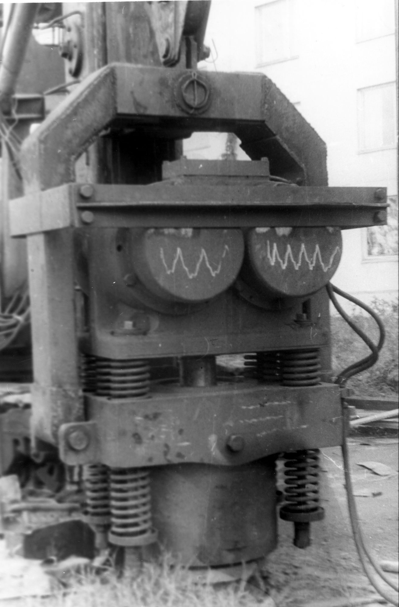
Strip Charts of the Basic Parameters of an Impact-Vibration Hammer for Various Values of i
Key:
1) Displacement of the impact component
2) Velocity of the impact component
3) Angular position of the eccentric
4) Time Marker
As stated above, the basic parameters that characterize the operation of the impact-vibration hammers (including the impact velocity for these hammers) are the reduced stroke speed restoration coefficient of the velocity upon impact, the nature of the variation in the acceleration of the vibration exciter and the position of the eccentrics relative to the displacement, i.e., the phase angle of movement between the displacement of the eccentrics and the exciter. The most suitable instruments for measuring the acceleration, velocity, and displacement of the vibration machines are accelerometers with piezoelectric elements, the electric signal of which is proportional to the acceleration. These accelerometers have small dimensions and mass, which is quite important for this application. Additionally their use in conjunction with integrating devices makes it possible to obtain and record the velocity (single integration) and displacement (double integration). Induction type seismic detectors are quite frequently used to evaluate the operation of the vibration machines; their electric signal is proportional to the rate of displacement and is recorded, as well as the signals of the accelerometer with a strip chart recorder. Sample outputs of this recorder are shown in Figure 13.
In the velocity detector the seismic mass, with a winding supplied with direct current, is suspended in the frame on springs, the rigidity of which assures a considerably lower frequency of its vibrations than the frequency of the exciter. As a result, during operation of the vibration mechanism the body of the detector effects vibrations together with the machine, and the seismic mass remains immobile even in the thrust mode.
The nature of rotation of the eccentric shafts is usually monitored with the aid of a pulse detector in the form of a small wheel of insulating material, on the periphery of which metal plates are placed equidistant from each other. The small wheel is placed on the eccentric shaft and in rotating shifts the places around the fixed electromagnet connected with the exciter. The pulses are noted on the recorder tape. One of the plates on the wheel, positioned in line with the eccentric, is longer than the other and consequently a sharper peak is obtained from it on the tape. At the same time, recording either displacement or velocity of the exciter makes it possible to assess the angle of shift of the phases between the positions of the vibration exciter and the eccentrics.
In the course of the design and testing of the units, there were two area which required the most attention from the designers. The first was the development of special, vibration-proof motors and the second was the selection of springs, both in terms of calculating their parameters and in the design and manufacture of actual springs that met these parameters.
Concerning the motors, based on tests at the VNIIstroidormash test rack the service load of the exciter was assumed to be 150g’s; the motors then had to be configured to endure 150 hours of this type of loading. The tests on these motors showed that the main reasons for motor damage were a) breaking of electrical wires and b) damage of the winding insulation and thus the short-circuiting. Problem (a) was eliminated by tightening the wires and the nuts which affix the electric wires to the motor.
To eliminate (b), the windings were twice coated by a special procedure involving both vacuum and pressure to fill all of the cavities inside the windings. This was done to eliminate any vibrations of the wires relative to each other. The development of this procedure was conducted jointly with the Electro-Technical Institute of Minelektrotekhprom. This Institute recommended special thermoplastic compounds which would act like a shock absorber between the windings during impact.
Once this procedure was formulated there were fifty (50) motors tested in seven sizes ranging from 2 to 17 kW. The service life of the motors which were made with these compounds was 200 hours under 200g loads. During the tests there was no damage to any motor. The results of the tests were submitted to the Electro-Technical Institute; the special technology was subsequently approved by Minelektrotekhprom.
The second main challenge in the development of these hammers was the situation with the springs. The springs had to remain elastic for deformations up to 100 mm at frequencies up to 16.7 Hz. In the process of development and testing of these springs it was determined that the maximum permissible torsion stress was 200-300 MPa; this value increased for smaller springs. Alloy steel was used for the springs.
In order to reduce testing time, a method of accelerating the tests was proposed. This involves computing the service life of the equipment by the formula
![]() (21)
(21)
where
- t1 = time of hammer operation in weak soils, minutes
- t2 = time of hammer operation in hard soils, minutes
- Q = service life of equipment, hours
- Q1 = hammer service life in weak soils, hours
- Q2 = hammer service life in hard soils, hours
For example, if we consider the case of t1 = 4 minutes, t2 = 6 minutes, Q1 = 500 hours and Q2 = 130 hours, then in this case Q = 280 hours. This is the equivalent of condensing the field driving of 1,600-1,800 piles into 280 hours of bench testing.
16 Model S-467 and S-467M at Stalingrad
The first broad practical application of the impact-vibration hammer took place in the construction of the Stalingrad power plant, where in the construction of the anti-filtration wall under the dam “Larssen-5” piles were driven to a depth of 13 m with the driving at the last site in sandstone of medium firmness.
The use of model VPP-2 (specifications are shown in Table 2) vibratory driver with power ranging from 55 to 75 kW assured the driving of said pile to a depth of 6-8 m; the presence of clay layers quite frequently stopped the driving of the sheet pile such that it was necessary to complete the driving with double-acting air/steam hammers with an impact energy of 180 kJ and a blow rate of 100 blows per minute. Driving the pile to the required depth was assured with a model S-467 impact-vibration hammer, with a power of 44 kW, an impact energy of 40 kJ, and a frequency of 480 blows per minute. More than 50 tons of piles were driven with the use of the S-467M impact-vibrational hammer, specifications for which are shown in Appendix B, Table I.
Table 2
Specifications for Vibratory Hammers
| Specification | VPP-2A1 | VP-1U1 |
| Electric Motor Power, kW | 55 | 60 |
| Eccentric Moment, kg-m | 11 | 93 |
| Frequency, Hz | 16,25 | 7 |
| Dynamic Force, kN | 250 | 180 |
| Total Mass, kg | 2200 | 7000 |
17 Model S-836 and Related Units
S-836 Hammer at Stalingrad
Subsequent studies aimed at improving the construction of impact-vibration hammers were transformed into hardware with the construction of an impact-vibration hammer, in which its head was placed on the pile freely without connection to it, and the vibration exciter was connected to the head with the aid of a spring system (USSR Author’s Certificate 210,035, Figure 3e). In this case the head performed a protective function, and its mass was selected to assure its immobility (or movement with a given amplitude) relative to the pile (Erofeev, 1966). This hammer construction assured transfer of the impact to the pile (bypassing the body of the head) through an anvil placed in the opening of the upper part of the head, and the reaction of the springs was absorbed by the body of the head during the upward movement of the vibration exciter. This scheme excluded the need for connecting the head of the hammer to the pile and thus the need for providing the head with mechanisms for these purposes, which substantially simplified operation of the machine.
During the development of such equipment, tests were conducted on an S-836 impact-vibration hammer, specifications for which are shown in Table 3. The tests were conducted by driving reinforced concrete piles in various regions of the USSR. Eighty-four such piles 10 m long, 350 mm square, and 3.5 tons in weight were driven with the S-836 in the construction of a collector for subterranean communications. This job site and the hammer are shown in Figure 14. The soils were characterized as shown in Table 3.
Table 3
Soil Characteristics for S-836 Job I
| Depth, m | Soil Type |
| 0-3 | deep, ice, water, grey and clayey sandy loam, of weak consistency |
| 3-7.5 | light-coloured and dark-grey load with a large amount of unrotted vegetable residue |
| 7.5-9 | yellowish-brown peat of weak consistency |
| >9 | heavy, bluish-grey sandy loam of medium consistency |
The average penetration velocity was 3.7 m/min, the average number of piles driven per shift was 13.5 (taking into account all lost time) and mean technical productivity was 16.8 piles. On the same job and pile driving rig an S-330 rod type diesel pile with 2.5 ton ram was suspended; it drove piles 10 m in length, 300 mm square cross section and weighing 2.8 tons. For all sixty-eight (68) piles driven, the mean penetration velocity was 1.47 m/min. Again with the same rig a VP-1 vibratory hammer (specifications shown in Table 2) with a power of 60 kW was suspended, and it drove piles to a depth of 3 m, after which driving stopped.
The S-836 impact-vibration hammer was tried for driving piles in the construction of a new mechanical plant, where the soils were characterized as follows: 0-1.5 m, fill with a large amount of broken brick, boards, domestic garbage; past 1.5 m, dry sand with gravel and pebbles. The attempt was unsuccessful; the piles were driven to a depth of only more than 3 m.
A substantial number of tests on impact-vibration hammers were conducted in Riga, Latvia, where they drove piles under dwellings. The soils in this region are characterized as soils of low and medium consistency. The piles were 300 mm square reinforced concrete piles, 10 m long. There were 496 of them driven with an average penetration velocity of 1.04 m/min. The mean driving time for the same piles with an S-330 diesel pile hammer was 0.83 m/min. Comparison with a vibratory hammer was not carried out on these piles.
Unfortunately, the hammers produced according to this scheme 1) had considerable weight, 2) did not assure the transfer of vibrations to the pile because it was damped by the body of the head, and 3) did not permit varying the operating mode of the vibration machine, i.e., passing from the impact-vibration mode to the impact mode and vice versa.
18 Development of the Hydraulically Adjusted VI-571
The shortcomings of (2) and (3) were eliminated after the creation of an impact-vibration pile driving machine with a combined action (USSR Author’s Certificate 338,590), the construction of which assured a) a substantial reduction in the mass of the head and b) the possibility of remote changing of the operating mode of the vibration machine. Item (a) was assured because the design of the hammer made it possible to connect the head with the pile to be driven during the upward movement of the exciter until it impacts the pile (the so-called “semi-free” head). Item (b) was assured by the introduction of a vertical hydraulic cylinder into the construction of the hammer, the rod of which was connected to the exciter, and the body with the head, which assured the fixation of the exciter with the head and simultaneously the head with the pile.
This hammer also addressed the builders’ need for the driving of reinforced concrete piles and shell-piles not only in loose soils but also in firmer ones, such as clay soils. Although they were used during the early stages of their development only in loose, water-saturated (sandy, muddy, etc.) soils, at the present time it is necessary to use them also in stiff soils of medium density (loamy, plastic-clayey, dry sandy and gravelly soils). The possibility of using impact-vibration hammers for driving piles in compacted soils, including permafrost, compact clays, etc., cannot be excluded either; however, the data obtained during the operation of vibratory hammers reveal that their use in compact soils results in a sharp decrease in the penetration velocity and sometimes in stoppage of the driving.
A number of organizations producing vibratory machines for driving piles conducted studies directed toward increasing the efficiency of the machines by regulating the frequency and dynamic force. These efforts did not furnish significant results. Another way of improving the drivability of the equipment is the employment of the method of combined driving. Here a vibratory hammer is used in loose soils and an impact-vibration hammer with diminished impact energy is used in compact soils, eliminating damage and destruction of the reinforced concrete shell-piles. Savinov and Luskin (1960) wrote:
…such a vibrating driver could be a machine that would operate in the vibration mode in non-tenacious and loose clay soils and would pass to the impact-vibration mode automatically or by simple switching when compact soil layers are encountered.
The VI-571 combined action impact-vibration machine developed during subsequent improvement of the vibration technology for driving piles was tested under both stand and job site conditions. The specifications for this machine are shown in Appendix B, Table I, and a diagram is shown in Figure 3f.
The purpose of the stand test was to verify the efficiency of the design in general and the frame in particular, and also to verify the accuracy of the actual calculated parameters of the machine. The stand tests were conducted on the same VNIIstroidormash test stand described earlier. For the possibility of installing a combined action machine on it, the movable component was placed on it, the upper part of which was a #45 I-Beam.
For the tests in the vibration mode the rods of the hydraulic cylinders were supported in the plates of the springs and through rods with the clamps of the vibration exciter to the anvil of the head. The extendible jaw was turned and its stop fixed the vibration machine relative to the stand. The power required and the amplitude of the vibrations were measured during the tests.
The purpose of the vibration machine tests in the impact-vibration mode was to verify the efficiency of the new type head. This involves the assurance of a reliable connection of the head to the stand during the travel of the impact component upward and a complete disconnection during its travel downward, releasing the pile from the head prior to the impact of the exciter.
The velocity and displacement of the vibration exciter, the power required and the mutual displacements of the head and stand were measured during the tests. The measured values were recorded on the tape of a strip chart recorder. A type IS-312 acceleration piezoelectric transducer and an SDM-132 amplifier in conjunction with an integrating attachment were used to measure the velocity and displacement. Measurement and recording of the mutual displacements of the head and stand were performed with the aid of rheostat detectors, an 8ANCh-7M amplifier and N-700 strip chart recorder. At first, one detector was placed between the head and the stand, but because the head swung relative to the stand, a second detector was installed.
The tests proceeded as follows:
- When the machine was not operating, the support of the clamping jaw was initially provided and clamped the beam of the stand (position 1.) The equipment was operated and measurements were performed.
- The gap was increased to 2 mm (position 2.) The operation of the machine was repeated.
- The gap was increased again to a value at which there was no connection of the head with the pile during the maximum upward travel of the vibration exciter (position 4). As before measurements were performed at each position of the support.
The test results revealed the following:
- The velocity of the vibration exciter at the time of impact in the first three positions of the support differs little; it had a value close to the calculated one (around 2.2 m/sec) and the vibrating hammer operated in a stable manner.
- When the support or stop was in the position at which there was no connection of the head with the pile, a reduction and exit of the vibrating hammer from the periodic operational mode were observed. The results of analyzing the mutual displacements of the head and stand: in stop position 1, the displacement of the head relative to the pile is 5 mm, in position 2, 5.7 mm, in position 3, 3-7 mm, and in position 4, 25 mm.
- When the movable stop was in position 2, the joint recording of the impact velocity of head displacement relative to the stand made it possible to establish that the impact is applied when the head and stand are disconnected, i.e., the head does not absorb the impact load.
Industrial tests on the combined-action impact-vibration machine were conducted by driving a light metal pile 4 m in length. The driving rate, power required and the noise level were measured during the tests. The purpose of the industrial tests was to compare the parameters obtained with the calculated ones, and also to compare the vibration and impact-vibration driving modes. The instrumental measurements were conducted on four (4) piles out of forty-two (42) driven during the tests. The results are shown in Table 4. Analysis of the test results show the following:
Table 4
Results of Field Tests of VI-571 Impact-Vibration Hammer
| Pile No. | Operating Mode | Range of Driving Depth, m | Mean Driving Rate, m/sec | Power Required,kW |
| 1 | V | 0-4 | 2.45 | 14.3 |
| 2 | IV | 0-4 | 3.1 | 11.2 |
| 3a | V | 0-2.65 | 2.6 | – |
| 3b | IV | 2.65-4 | 3 | – |
| 4a | IV | 0-2.5 | 3 | – |
| 4b | V | 2.5-4 | 2.5 | – |
The construction of the impact-vibration combined-action pile driving machine is efficient, i.e., the machine can operate in both the vibration and impact-vibration modes with the given parameters; the machine can be switched off from one mode to the other by remote control without turning the machine off.
During operation in the vibration mode, the head assures its reliable connection with the pile and with the vibration exciter.
When working in the impact-vibration mode, the upward travel of the vibration exciter assures its connection with the pile, and during downward travel the frame does not make contact with the pile.
Unfortunately, it was also noted that the hydraulic apparatus for changing the operating mode of the vibration machine is not sufficiently reliable in operation and required a special power pack for the electric machine.
Such a design of an impact-vibration hammer was readily actualised with the creation of vibration machines for driving sheet piles, rolled metal elements, etc., but caused difficulties when driving reinforced concrete piles and, in particular, reinforced concrete pile shells.
19 Machines With Combined Action
As the development and use of these machines progressed, it became apparent that one very useful feature for an impact-vibration hammer would be to have the ability to operate either in a purely vibratory manner or in an impact-vibration mode. As mentioned before, Tsaplin accomplished this on his first machine by blocking the springs. However, he did this only to determine whether vibrations or impact-vibrations only for comparison purposes.
A machine that could transfer its operation from one mode to the next could a) use the more efficient operation mode at will, b) lengthen the life of the bearings by reducing the impact load time on them, and c) reduce the possibility of pile damage during impact. Such a device combines the energy control features of impact hammers with a very comprehensive method of changing the method of energy delivery to the pile, thus opening the possibility of a hammer useful for virtually any type of driving the hammer was large enough to manage.
While Tsaplin’s spring blocking is a classic example of a job site improvisational technique that is common on both American and Russian job sites, for machines in serial production and for their maximum productivity this or other related techniques a more automatic method needed to be developed.
To attempt to solve this problem, a vibratory driver with a power of 50 kW, elastically connected with the pile (the so-called “vibratory hammer with an impact attachment”) was developed precisely for the purpose of intensifying the driving of heavy reinforced concrete piles in general and shell piles in particular. The tests on it under industrial conditions were conducted on construction objects in Norilsk, a city in Siberia above the Arctic Circle, where about 1000 350 mm square reinforced concrete piles were driven into heavy clay and “high temperature” (up to -1.5°C) permafrost. The test results obtained provided the basis for confirming that the introduction of the impact attachment that makes it possible for the vibratory hammer to operate in the impact-vibration mode is industrially useful and economically justified.
However, the tests revealed that such a design has shortcomings, primarily 1) the impossibility of remote control to change from one mode to the other and 2) the complexity of spring adjustment. Similar difficulties had been encountered with machines with hydraulic adjustment. Additionally contractors were looking to be able to drive larger piles, such as heavy reinforced concrete piles are shell piles up to 1600mm in diameter.
20 Development of the Electromagnetically Adjusted SP-53
To address all of these problems, in 1967 the SP-53 impact-vibration hammer was developed. This hammer had the following features:
- Ability to drive heavy tubular piles (both steel and concrete) into the ground. This included reinforced concrete shell piles 600-1000 mm in diameter
- Rigid connection of the frame with the pile by familiar means (hydraulics, pneumatics, or a mechanical connection)
- A system with both an electromagnet and springs were placed between the vibration exciter and the frame (USSR Author’s Certificate 249,296). The spring system was installed to assure a rigid connection of the vibration machine with the pile when the magnet is switched on, i.e., a vibration mode of operation. When the electromagnet is switched off, the exciter was connected with the pile top only elastically by the springs, which assured an impact-vibration mode.

An electromagnet rigidly connected to the head and connected by springs with the body of the exciter was installed between the exciter and the head. The attractive force of the electromagnet is equal to the dynamic force of the rotating eccentrics. When the electromagnet is switched on, the body of the exciter is rigidly connected with it and with the head, and the entire system is a single unit, i.e., during rotation of the shafts the machine operates in the vibration mode, producing vertically oriented vibrations. When the electromagnet is switched off, the exciter remains connected to the head only by the spring connection and, when the eccentrics rotate, it impacts the electromagnet and through the head to the pile. The kinematic connection between the shafts and the electric motors is absent; instead, power is transmitted to one eccentric shaft vertically with the aid of a system of gears.
The technical specifications for the SP-53 unit are given in Appendix B, Table II, a diagram is shown in Figure 3g, and a photograph of the unit in Figure 15.
Prior to field use, the unit was tested at “TsNIP”, the Central Scientific Research Test Area of VNIIstroidormash. The tests were conducted on the test stand described earlier. The tests were conducted in the following sequence:
- The characteristics of the electromagnet were plotted.
- The electric motors were started up separately for their regulation and verification.
- The counterrotation of the eccentrics was synchronized.
- The vibration mode of the unit was checked.
The attractive force of the electromagnet was determined at various gap values, which were created by a device with dielectric spacers placed between the electromagnet and the 100 mm thick steel plate, placed on top of the magnet. Two 100 ton hydraulic lifting jacks, supported with coupling rods on the steel plate, were used to remove the plate. The plate removal effort was calculated by the hydraulic pressure. Calibration of the electromagnet made it possible to establish its attractive force to be 35 tons at a gap of 1 mm.
Vibration Mode: Tests on the vibration driver in the vibration mode were conducted in a cycle of fifteen minutes of operation and ten minute breaks. Both the power of each electric motor (with a wattmeter-recorder) and the amplitude of the vibrations of the vibration driver were measured during the tests. The tests revealed the following:
- During the separate start-up of the electric motors, a different interval was established between their starting torque. A time interval of two (2) seconds is enough for the separate start-up of the two electric motors.
- Synchronization of the shaft rotation occurs practically instantaneously and no oscillation of the vibration driver body takes place in the start-up period.
- Both electric motors are loaded nearly equally during operation.
- No overheating of the electric motors, electromagnet, or other units of the vibration driver was noted.
Impact-Vibration Mode: The tests on the vibration driver in the impact-vibration mode were carried out in a cycle of five (5) minutes of operation and ten minute breaks. The same parameters were measured during the tests as before. The tests revealed the following:
- Operation in the impact-vibration mode is characterized by large vibrational amplitudes, and the power consumption doubles from that of the vibration mode.
- The vibration driver operates in a stable manner in the impact-vibration mode.
- The amplitude of the vibrations can be regulated by compressing the springs. The amplitude and power decrease when they are tightened.
- The body of the vibration driver is shifted to the sides during the impacts. It was possible to eliminate the horizontal displacements of the body when thick-walled sleeves are installed on the rods inside of the springs; the sleeves fixed the exciter relative to the head.
During the entire fifteen (15) hour duration of the stand tests, no breakdowns were observed. The efficiency of the construction on the whole was established, methods of regulating the amplitude of the vibration and the power of the vibration driver were designated and the theoretical conclusions on the impracticality of regulating the operational mode by modifying the attractive force of the electromagnet were confirmed experimentally.
Jobsite Tests: After the laboratory tests a job site test was performed on six (6) reinforced concrete shell piles 600 mm in diameter and 24 m in length (two sections of 12 m each) were driven.
The tests confirmed the following:
- The transition from mode to mode during the operation of the vibration driver is effected by remote control and the transition time does not exceed 30 seconds.
- The driving intensity is higher in the impact-vibration mode than in the vibration mode.
Thus, when the driving of a shell pile stopped in the vibration mode, shifting to the impact-vibration mode assured further driving.
Impact-vibration hammers are an interesting and productive application of technology. The machines have the potential to dive a wide variety of piles, especially when configured to operate in both vibration and impact-vibration mode.
Recognizing this potential, in the years from 1954 to 1970 Russian investigators conducted a great deal of research relating both to the mechanics of operation and the design, along with the industrial application of impact-vibration machines, have involved the following:
- A detailed study of the theoretical principles, practical applications and industrial actualisation of the vibration method of driving piles, and establishment of the most feasible areas of its application.
- Establishment of the principle of the further intensification of the driving process by application of the vibration method to be the combination of vibration with impact, i.e., employment of the impact-vibration method of driving piles.
- Proposal of a number of designs and methods for their actualisation, which permit the creation of machines that assure the transfer of impact-vibration, vibration, and impact (with a high impact frequency) modes to the pile, with experimental confirmation of the efficiency.
- The working out of the theoretical principles and methods for the engineering calculation of impact-vibration machines.
Unfortunately, although in many cases these machines were and are used on many jobsites, progress on these machines in the Soviet Union was slowed to a virtual standstill by a) technical difficulties related to the adjustment of the output of the machines, and b) the general slowing down and in many cases the stoppage of progress of the Soviet economy during the Brezhnev years, which discouraged innovation and improvement in techniques. Such a condition led in no small measure to the disintegration of the Soviet Union in 1991 and the establishment of the Russian state. In both cases, it remains to be seen what the future might hold.
Appendices
Appendix A
Special Topics on the Soviet System
Institutes and Their Names
There are several names mentioned in this paper which look very strange to the American reader. These are names of the various institutes and facilities which were involved in the work. All of these were parts of the state; their names tend to be long, so generally speaking Russians shorten their names into acronyms or near acronyms. A well known example of this is the old Soviet news agency Tass; the name is in reality a true acronym for “Telegrafnoe Agentstvo Sovietskogo Soioza” (Telegraph Agency of the Soviet Union).
A list of such state agencies mentioned in this article is as follows:
- Minelektrotekhprom — Ministry of Electro-Technical Industry of the USSR.
- TsINTIAM — Central Institute of Scientific and Technical Information on Automation and Machinery Manufacture
- TsNIP — Central Scientific Research Test Area
- VNIIstroidormash — Moscow Scientific and Production Amalgamation of Construction and Road-Building Machinery
Author’s Certificates
According to the Great Soviet Encyclopaedia (1969), a Soviet author’s certificate “confirms the author’s (inventor’s) claim to authorship and his right to a reward and other rights and benefits, and government’s exclusive right to use the invention. In issuing an author’s certificate, the state assumes the task of implementing the invention and of deciding whether its introduction is advisable. All socialist organizations may, without special permission, utilize an invention for which an author’s certificate has been issued.”
With the end of the Soviet Union and the introduction of elements of a market economy, the author’s certificates gave way to patents and thus passed into history; as of 1 January 1994, the author’s certificates are void.
Appendix B
Specifications for Impact-Vibration Hammers
Table I
Impact-Vibration Hammers Produced in Russia
(experimental and production units.)
| Size | S-835 | VM7U | VM-9 | S-834 | S-836 | S-467M | VI-571 |
| Mass of Striking Part, kg | 700 | 670 | 700 | 650 | 1400 | 2000 | 650 |
| Number of motors | 2 | 2 | 1 | 2 | 2 | 2 | 2 |
| Power of each motor, kW | 7.5 | 7 | 14 | 5.5 | 13 | 22 | 5.5 |
| Total Power, kW | 15 | 14 | 14 | 11 | 26 | 44 | 11 |
| Rotation frequency of electrolifter, RPM | 1440 | 1450 | 1440 | 960 | 960 | 960 | 960 |
| Blows per minute | 480 | 1450 | 1440 | 480 | 480 | 480 | 320 |
| Frame Type | A | B | B | C | C | C | |
| Length, mm | 880 | 1150 | 1150 | 850 | 1020 | 1150 | |
|
Width, mm | 700 | 1050 | 1040 | 750 | 880 | 1000 | |
|
Height, mm | 1120 | 1100 | 1360 | 1350 | 1870 | 1940 | |
| Machine mass, kg (without cable and control panel) | 1100 | 1400 | 1680 | 1800 | 4500 | 6500 | 1450 |
Frame Type Code:
- Mechanical
- Wedge Shaped
- Freely Falling
Table II
Specifications for SP-53 Impact-Vibration Hammer with Electromagnet
| Vibration Exciter | |
| Dynamic force of the eccentrics, kN | 313.6 |
| Eccentric moment, kg-m | 220 |
| Frequency of the vibrations, RPM | 400 |
| Number of Eccentric Shafts | 4 |
| Electric Motor Type | AOPVV 291-6 |
| Power, kW | 50 |
| Number of Rotations, RPM | 980 |
| Voltage, V | 380 |
| Number of Motors | 2 |
| Electromagnet Attractive force, kN | 313.6 |
| Gap @ Rated Attractive Force, mm | 0.2 |
| Voltage @ exit of selenium rectifier, V | 275 |
| Type of Current | DC, full wave rectification |
| Dimensional and Weight Data | |
| Mass of the vibration driver (without head), kg | 7000 |
| Overall Dimensions, mm | 1650 X 1300 X 3400 |
Table III
Impact-Vibration Hammers Produced in Japan
| Manufacturer | Nippei | Toyota | ||||
| Size | NVH-30 | NVH-50 | NVS-30 | TM-10 | TM-20 | TM-40 |
| Mass of Striking Part, kg | 3000 | 3000 | 3000 | 1500 | 2500 | 3500 |
| Number of motors | 1 | 1 | 1 | 2 | 2 | 2 |
| Power of each motor, kW | 22 | 22 | 22 | 7.5 | 15 | 30 |
| Rotation frequency of electrolifter, RPM | 980 | 980 | 980 | 820 | 680 | 680 |
| Blows per minute | <1000 | Variable | ||||
| Frame Type | F | F | A | G | G | G |
| Length, mm | 970 | 930 | 820 | 850 | 1170 | 1170 |
| Width, mm | 820 | 820 | 770 | 840 | 1060 | 1060 |
| Height, mm | 3750 | 3600 | 3000 | 1500 | 1850 | 2300 |
| Machine mass, kg (without cable and control panel) | 3500 | 3500 | 3500 | – | – | – |
Frame Type Code:
- Mechanical
- Wedge Shaped
- Freely Falling
- Hydraulic
- Carving
- Pneumatic
- Mechanic and Pneumatic
Table IV
Impact-Vibration Hammers Produced in Poland
| Size | W-101 | BC-6 | BC-9EH |
| Mass of Striking Part, kg | 405 | 560 | 65 |
| Number of motors | 1 | 2 | 2 |
| Power of each motor, kW | 10 | 2.5 | 2.2 |
| Rotation frequency of electrolifter, RPM | 910 | 910 | 1440 |
| Blows per minute | 455 | 455 | 1440 |
| Frame Type | D | E | B |
| Length, mm | 700 | 700 | – |
| Width, mm | 570 | 800 | – |
| Height, mm | 1700 | 1400 | – |
| Machine mass, kg (without cable and control panel) | 1000 | 1050 | 105 |
Frame Type Code:
- Mechanical
- Wedge Shaped
- Freely Falling
- Hydraulic
- Carving
- Pneumatic
- Mechanic and Pneumatic
Table V
Impact-Vibration Extractors for Sheet Piles
| Size | VI-592A | Sh-2 | MSh-2 | MSh-2M | SP-83 |
| Mass of Striking Part, kg | 1700 | 1900 | 2000 | 2000 | |
| Number of motors | 2 | 2 | 2 | 2 | 2 |
| Power of motor, kW | 13 | 22 | 22 | 22 | 17 |
| Rotation frequency of electrolifter, RPM | 960 | 960 | 960 | 960 | 480 |
| Blows per minute | 480 | 960 | 960 | 960 | 480 |
| Impact Energy, kJ | 2.7 | 2.2 | 2.2 | 2.2 | 2.85 |
| Dynamic Force, kN | 240 | ||||
| Maximum Length of Sheet Piles for Extraction, m | 17 | 10 | 20 | 10-20 | |
| Maximum Weight of Sheet Pile for Extraction, metric tons | 1.5 | 2 | |||
| Minimum Required Pulling Capacity of Crane, metric tons | 20 | ||||
| Frame Type | A | D | D | D | |
| Length, mm | 1110 | 1210 | 1210 | 1210 | 1370 |
| Width, mm | 785 | 910 | 1050 | 1175 | 960 |
| Height, mm | 3300 | 3525 | 3710 | 3710 | 2750 |
| Machine mass, kg (without cable and control panel) | 3600 | 3300 | 4200 | 4100 | 4900 |
USSR Author’s Certificates
- 210,035 — Vibrating Hammer (L.V. Erofeev, V.I. Chenchikovskii et. al). Bulletin of Inventions #18, 1969.
- 338,950 — Vibrating Hammer for Driving Piles, Tubes, and Similar Elements (L.V. Erofeev, A.V. Bauman, V.I. Chenchikovskii et. al.). Bulletin of Inventions, #10, 1972.
- 249,296 — Vibrating Hammer (L.V. Erofeev, L.N. Petrunkin, A.G. Sivstev, V.S. Morgalio, and Yu. V. Ditrikh). Bulletin of Inventions #37, 1974.


4 thoughts on “Russian Impact-Vibration Pile Driving Equipment: Chapter 3, Research and Development of Impact-Vibration Hammers, and Appendices”