Welcome to vulcanhammer.info, the site about Vulcan Iron Works, which manufactured the durable air/steam line of pile driving equipment for more than a century. Many of its products are still in service today, providing reliable performance all over the world. There’s a lot here, use the search box below if you’re having trouble finding something. Also look at the end of an article, there are helpful links to more information with every post.
An Overview of Tapered Pipe Threads, and Their Application at Vulcan
It’s hard to imagine that much of our technology is underpinned by very old, basic standards that year after year simply “do their job” without much regard. One of those is tapered pipe threads. This is a brief overview of same, and specifically the “National Pipe Taper” or NPT threads. Much of this material comes from the American Machinists’ Handbook by Fred Colvin and Frank Stanley, Second Edition (1914).
Most screw threads are “straight threads,” i.e., the diameters of the threads (outside, pitch, inside) are constant along the length of the threads. Tapered threads by definition can only work for a limited length, but when pipes are connected, that’s fine. Like any other taper lock, tapered threads have an additional wedge effect, which means that they can seal fluids in the pipe (or outside of it.)
Originally these pipe threads were referred to as “Briggs standard threads” after Robert Briggs who came up with them. In 1886 these were adopted as a standard by the American Society of Mechanical Engineers and various manufacturers. They have varied little since that time. They have been a durable standard for leak-resistant, permanent (and semi-permanent) connections ever since.
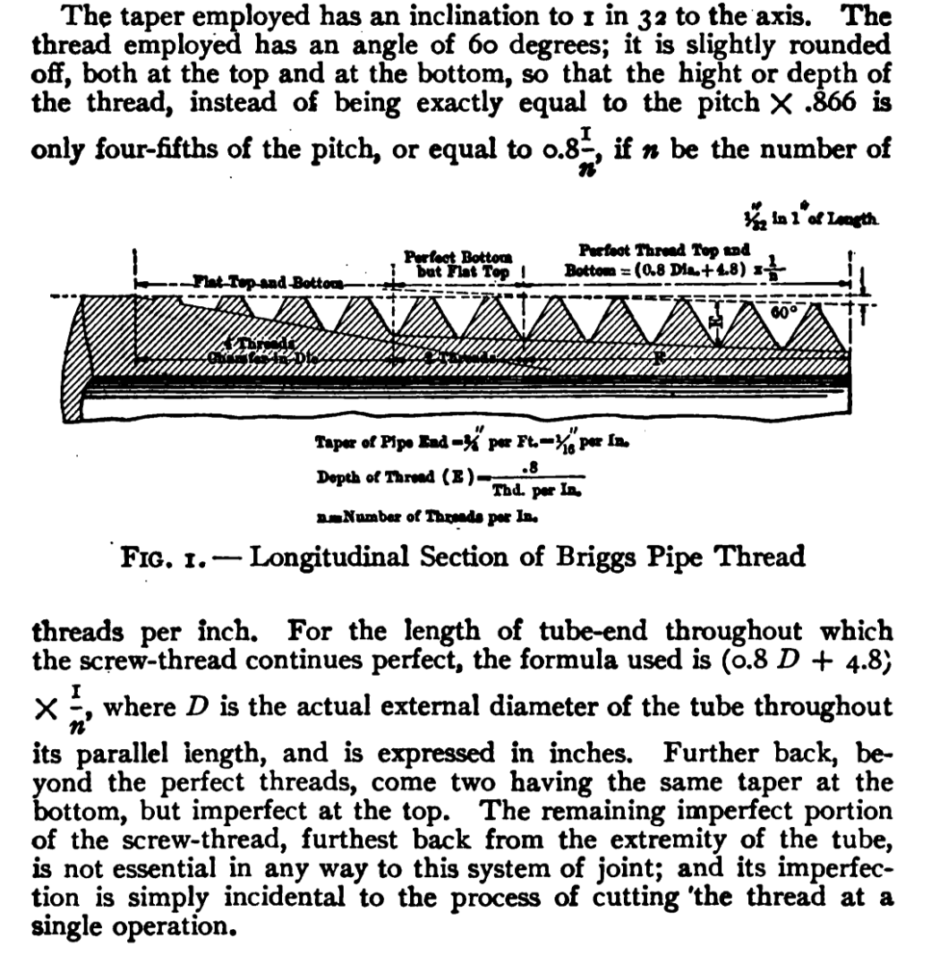
An overview of the “Briggs standard thread” is below.
As noted above, only the “perfect” threads (in one way or another) contribute to the sealing/joining of the pipe thread.
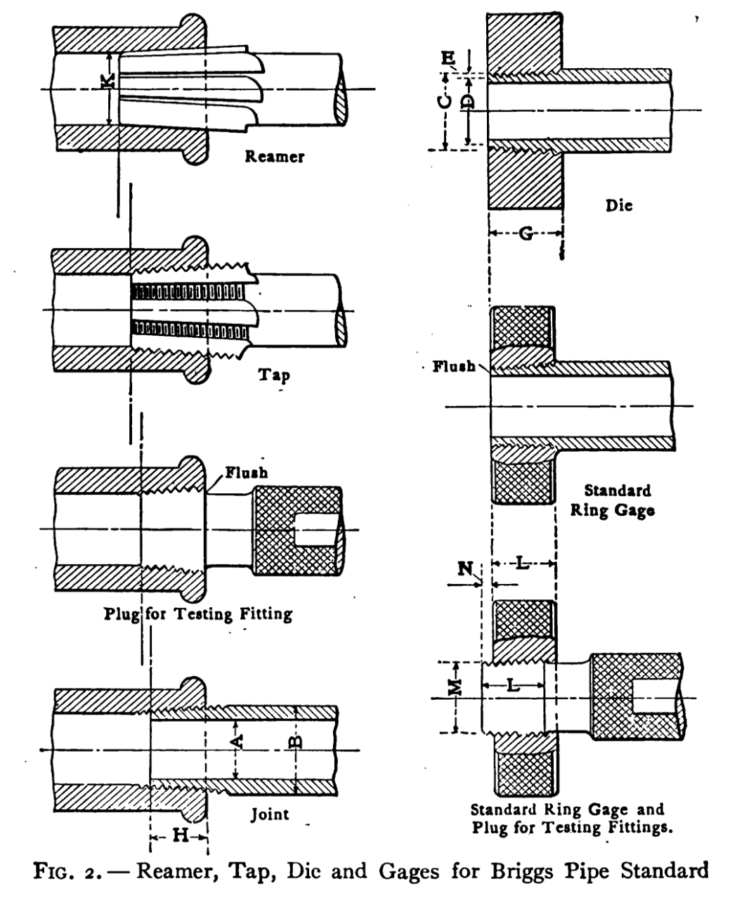
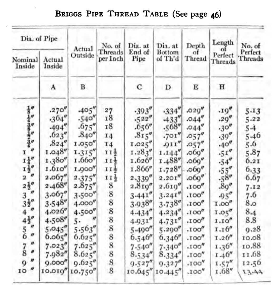
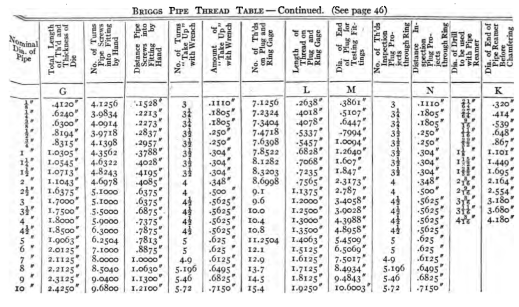
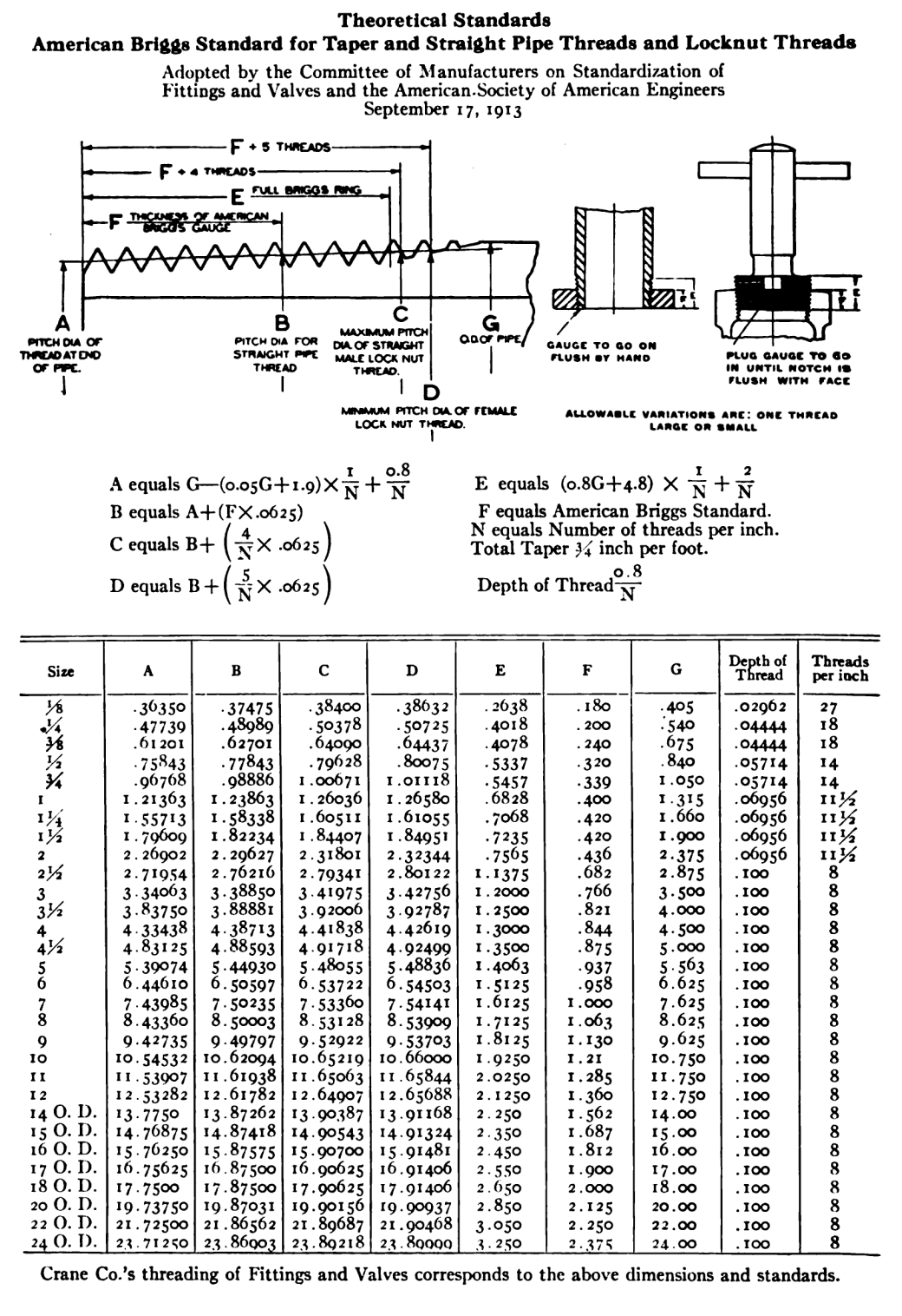
The overall dimensions of the various sizes of tapered pipe threads are shown below, with a diagram showing the types of gauges used to check the threads.
The tapered reamer was one item Vulcan seldom used; the usual procedure was to tap drill the hole and then use a tap for the threads in question to put the threads in the hole. Below are some tap sizes for NPT (National Pipe Taper, or Briggs) threads.
Tap drills for National Pipe Taper threads. The “Briggs” values are for the NPT threads; the Whitworth are for their UK counterpart, which were never as popular as the NPT/Briggs threads. The drill size for the 2″ pipe tap should read 2 3/16″. In reality there is a little “wiggle room” for the tap drill size, as is the case with straight threads.When threading a pipe, a die is generally used. The “actual inside diameter” can vary; the table here is closely related to Schedule 40 pipe. It can obviously be smaller for higher pressure applications and those where the mechanical strength of the connection needs to be larger (as with pressure gauges.)
A more detailed treatment of the threads as the pipe and hole threads interface is shown below.
Theoretical standards for the NPT/Briggs standard pipe threads, with a more complete treatment of the perfect and imperfect threads, which is important in the design of pipe threaded holes, specifically how deep they need to be. This comes from “The Crane World” magazine, January 1919, from the Crane Company, a leading manufacturer of valves. When the Crane Company was established in 1855, it was near Vulcan’s facility and in fact Vulcan’s founder, Henry Warrington, was Crane’s first customer, placing an order for box castings (a notoriously difficult shape to cast) and other parts for locomotives, which Warrington was making at the Vulcan Foundry. In his later years, after his sons were active at Vulcan and their other activities, Warrington worked at the Crane Company.
The pipe taper standard was wildly successful, and is used in everything from home plumbing to high-pressure hydraulics. In the oilfield the standard was so successful that it’s widely used even in places where metric standards are the norm
As far as Vulcan is concerned, Vulcan used the standard in many of its products, both the air/steam hammers and later the hydraulic vibratory hammers, where they were used for pressures up to 5000 psi. This was due to their durability, ability to resist vibration (a must with any Vulcan product) and their flexibility in radial orientation. With a pipe thread there is a point where it’s “tight” but it can generally be tightened a little further, thus allowing some flexibility in the orientation of parts. One thing Vulcan learned with pipe threads was, although they are designed to seal with their taper, the use of some kind of “pipe dope” or sealant is very important.
Below are some applications of pipe threads in Vulcan hammers.
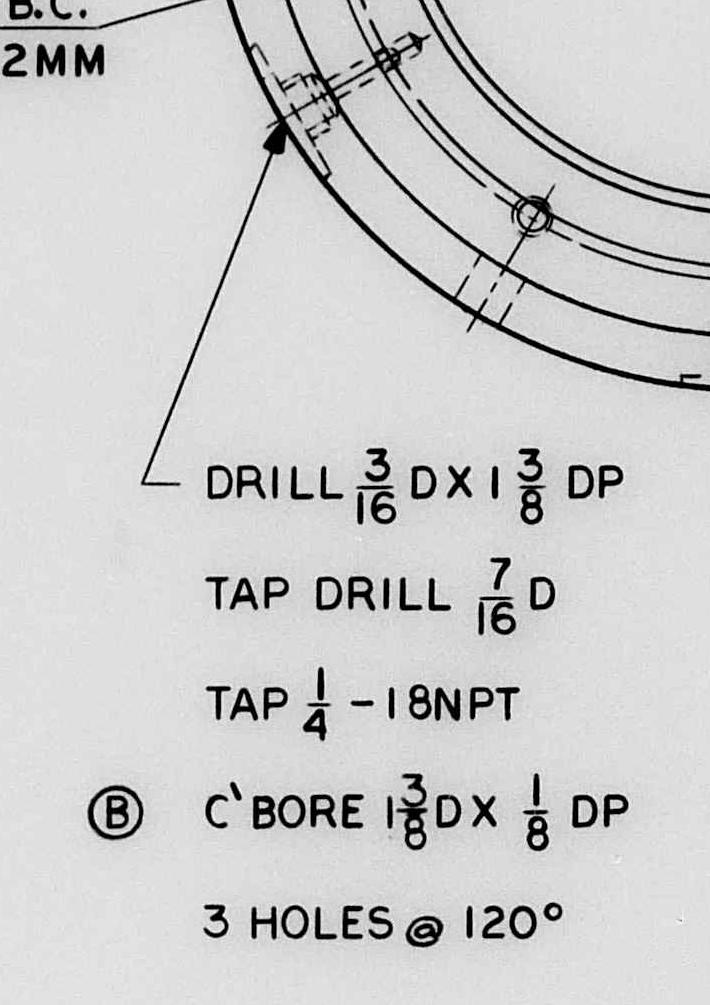
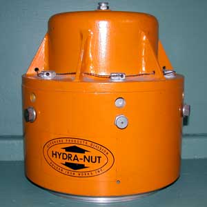
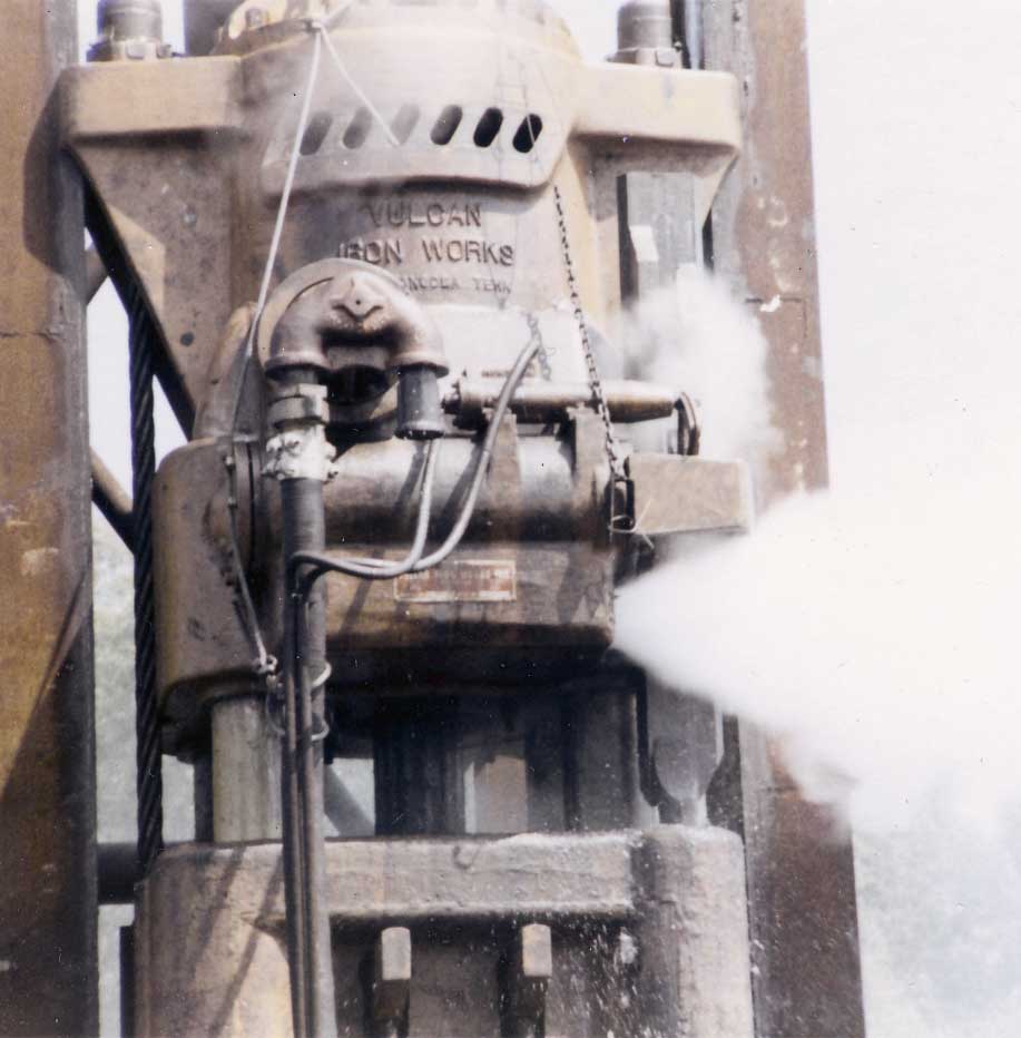
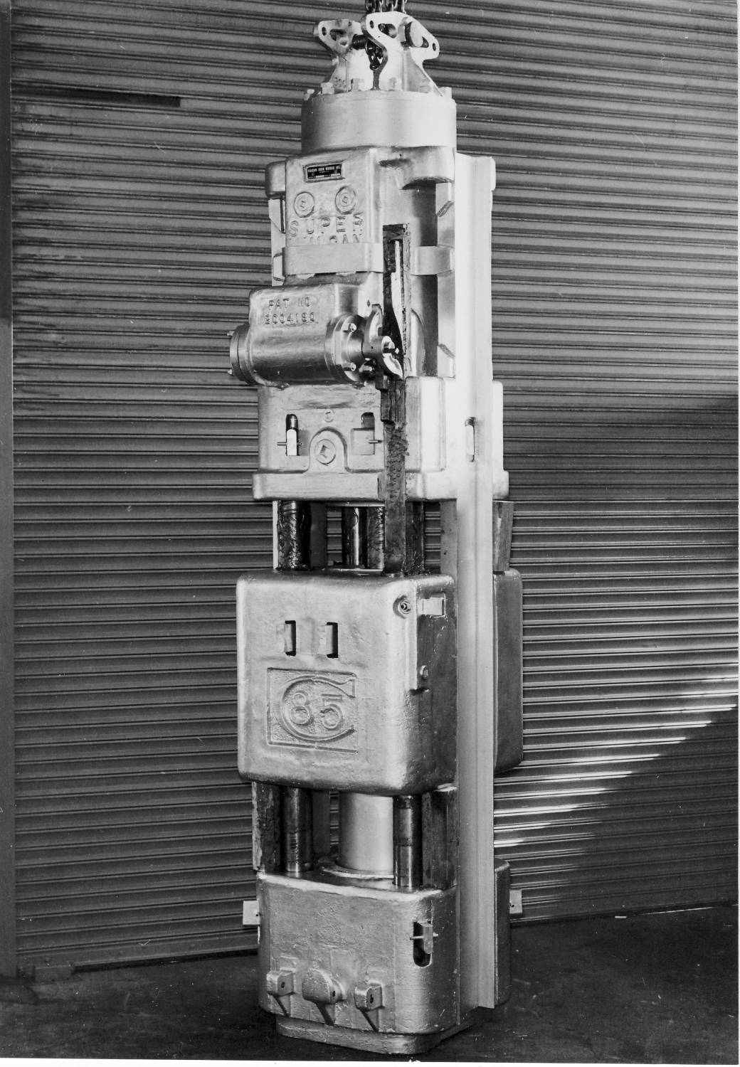
A Vulcan drawing “callout” for pipe threads, in this case small ones for the grease fittings on the Hydra-Nut.The “outside” of the Hydra-Nut (U.S. Patent 3,938,427.) Introduced in the 1970’s to directly replace the cable nuts (as shown above,) the Hydra-Nut simplified the process of tensioning the cables. The Hydra-Nut was screwed on without the cast thread protector cap on the top, the cable was lightly tensioned with a “manual jack,” the threaded sleeve was screwed down on the cable fitting and tightened against the jack body, the manual jack removed and thread protector cap replaced (aligning the flats on the cable fitting with those on the cap,) then the chamber was pressurised through the grease fittings to the pressure where the cables would have their proper, full tension. The weakness of the Hydra-Nut was in the grease fittings; should dirt or paint get in them, the chamber would depressurise and the cables would be loose. This was more probable when Zerck fittings were used than with the button head fittings as shown. Vulcan addressed this issue in the 1980’s with the Auto-Jack, which altered the Hydra-Nut by adding an internal cable nut with the integral jacking cylinder, which was then depressurised when the cable achieved proper tension.A call out for a pipe flange on a Vulcan offshore hammer. Note that now, instead of tap “drilling,” we’re forced to bore the hole before putting the pipe tap in.A close-up of the 040 cylinder during exhaust. The large hose is the steam hose that powers the hammer, the small hoses are the Vari-Cycle hoses that shift the trip shifter one way or the other to vary the stroke. The hose is connected to the hammer through a connector which is screwed in the large pipe caps on the double pipe flange in the front of the hammer.Vulcan 85C Hammer. Note that, towards the top of the cylinder are two pipe plugs. These are installed into tapped tapered pipe fitting holes. (There are actually four of these, two are covered by the plate referred to as a “belly band.”) Behind them is a cored passageway between the valve and the top of the cylinder. These holes helped to support this core during casting but had to be plugged for use, and the pipe plugs were the ideal way of doing this.


2 thoughts on “An Overview of Tapered Pipe Threads, and Their Application at Vulcan”