

L.V. Erofeev, VNIIstroidormash
V.A. Nifontov, VNIIstroidormash
D.A. Trifonov-Yakovlev, VNIIstroidormash
D.C. Warrington, Vulcan Iron Works Inc.
This article first appeared in the First June 1993 issue of Pile Buck, and is reproduced here with some updates. Related information is as follows:
- Click here for trip reports of the one test of this device in North America.
- Detailed technology specifications for the next generation of pile cutters based on this method are available; click here if you are interested in contacting us about this.
- Vulcan’s obtaining the patent rights for this device was a long process; for its hilarious conclusion, click here.
Introduction
When the driving of a concrete pile is complete, the next step is to connect the top of the pile with the structure it is holding up. To do this, it is frequently necessary to have the reinforcing bar protrude above the top of the pile. There are two basic ways to accomplish this:
- fabricate the pile with protruding reinforcing bar or cable; or
- to cut off the top of the pile in such a way as to leave the reinforcing bar or cable exposed for connection.
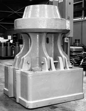
Method (1) would seem to be the most straightforward, but there are many hidden pitfalls. The first is the obvious one, i.e. in the handling of the pile, it is easy to damage the protruding steel. Another is related to driving the pile with exposed steel. For many years, hammer manufacturers cast pedestal driving heads, as shown in Figure 1, that would allow enough space for protrusion. Many manufacturers have abandoned pedestal driving heads because of reliability problems, since the allowance for the reinforcement cage leaves little room for the steel itself. Another solution is to use a three piece cap arrangement, with one cap mating to the hammer, another the pile and a piece of pipe in the middle. The protruding reinforcement steel protrudes into the inside of the pipe. While this has been used successfully, it results in a three piece cap with the attendant weight and additional interfaces for the driving energy to pass through.
Method (2) requires that whatever method is used to cut off the pile allow the reinforcement steel to remain after the top concrete is gone. Although there are methods to accomplish this manually, it would be more productive and consistent to use an automatic device to accomplish the task. This paper describes such a device, its development and its application.
Development
Russia is a place where concrete piles play an important role in foundations therefore, it should not be surprising that the problem of concrete pile cut-off should occupy the attention of Russian researchers and construction organizations. Attempts to mechanize this process were made in the USSR in 1960’s when there were manufactured devices which cut concrete and reinforcement bars by rotating diamond-metal disks (concrete pile saws), as well as devices which crushed pile concrete by effort perpendicular to the pile axis, which exposed reinforcement bars for their further cutting by any method available. There were also developed and produced devices which 1) provided pile cracking at a predetermined level, 2) acted in a “clipper” mode to cut piles, 3) twisted the pile at a predetermined level, and 4) cut the pile by heat, crushing, ultra-sound and other methods.
For a variety of reasons these methods have not found widespread use in Russian construction works and up to now the process of protruding pile parts breaking and removal is not mechanized. It is carried out manually concrete crushing is performed by jackhammers such as are used in coal mines reinforcement bars are then cut by electric or resistance welding, gas or flame cutting.
Through extensive intelligence gathering, Russian organizations kept track of the development of pile cutters (automatic pile cutters) produced outside of the country. Amongst them there are devices produced by “Sanva Kizai” (Japan), “Diaber” and “Pilecut” (Switzerland), “HPSI” (USA), “Taets” (Holland), etc.. During analysis of these devices it was found out that all of them are based on the principle of pile concrete crushing by effort applied in transverse direction perpendicular to the pile axis. As a result of this effort the reinforcement bars were exposed and then cut by different ways at a predetermined level. It is necessary to note that all the operations concerning cutting of reinforcement bars are carried out manually in all of these machines.
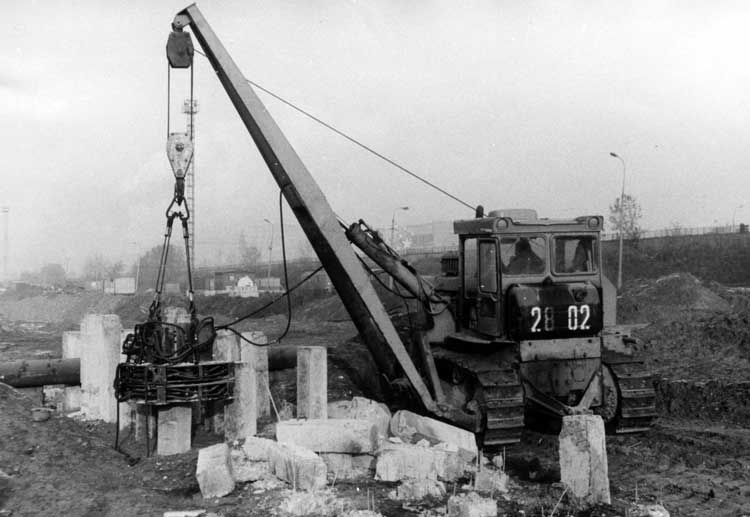
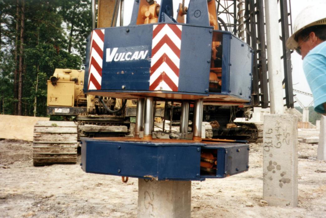
In cooperation with the Far East Institute of Construction, NPO “VNIIstroidormash” developed a new type of concrete pile cutter. These organizations carried out both scientific research and experimental tests using special test racks a prototype model being tested is shown in Figure 2. The researchers discovered that, with transverse compression of the pile at two levels and an application of a longitudinal breaking force, pile breakage will take place without deformation of the reinforcing bars (the concrete then moves relative to the reinforcing bars.) The researchers also discovered the basic parameters of the machine, such as the sizes of the compressing plates and the value of the compressing force which provides tight and reliable compression of the pile while preventing uncontrolled pile breaking. This discovery, coupled with discoveries in the nature of pile cracking, enabled these organizations to develop the new type of pile cutter, which basically combined the bond separation and the pile cracking in the same area of the pile, the cracking taking place both in the same plane as the bond failure and also above and below it. The index number of this machine is SP-88 (SO-270.) It has been manufactured both by VNIIstroidormash’s own pilot factory and a production factory. Such as unit is shown in Figure 3. This pile cutting machine was patented in the United States (U.S. Patent number 4,979,489).
Construction and Operation

The principle behind the new pile cutter is shown in Figure 4. According to this method, the pile (1) is compressed by two hydraulic grips (2) and (3) located at two levels near each other which provide uniform pile compression at all four side planes (Figure 4a). Then, vertical force parallel to the pile longitudinal axis is applied for purposes of completing the cutting process (Figure 4b). The location of pile concrete breaking level is determined by tension concentrators (4) which are installed at the hydraulic grips. The basic design of the pile cutter provides simultaneous breaking of both the reinforcing bars and the concrete, but the design may also provide for the protrusion of the reinforcement bars for their further embedment into a cast-in-place pile cap. Having broken the pile, the machine can also carry the cut-off pile section away for proper disposal.
A more detailed view of this device is shown in Figure 5. It consists of two grips (1) and (2) located one under another which are interconnected by the break cylinders (3), whose axes are parallel to the pile axis. Each grip in its turn consists of clamping sections (1a) and (1b) which are connected with each other by pile compression horizontal cylinders (4) which are attached to these sections by hinges. On the contact side of the pile each clamping section is completed with changeable plates (5). These plates have corrugated surfaces to provide tight contact with the pile and prevent sliding during pile breaking. Moreover, triangular teeth are welded into the lower parts of the upper grip changeable plates. These teeth act as tension concentrators which during pile compression dig into the pile and provide concrete cracking at the plane of breaking.

The pile cutter is completed with four (4) vertical struts located at the upper grip which are intended for suspending the pile cutter off of the crane for handing of both the pile cutter and the pile parts which are removed during operation. Typical suspension of this device is shown in Figure 3. The design of the grips consists of hinged and interconnected sections. Special rod synchronizers guarantee pile compression of square concrete pile, whether the pile is actually square or not (frequently the pile is in reality a parallelogram or trapezoid).
The pile cutter is used in combination with a hoist device of at least three metric tons load capacity to handle both the pile cutter and pile cut offs. If the hoist device is hydraulically operated the pile cutter can be driven from the hydraulic system of the crane and controlled from the operator cabin if the load hoist device is not hydraulically operated the pile cutter is driven from a special separate power pack which may be included with the pile cutter. This power pack may be driven from an electric motor or an internal combustion engine.
The pile cutter hydraulic system is completed with three (3) flow dividers to provide synchronized motion of the four vertical break cylinders during their extension, thus providing parallel movement of upper grip relative to the lower one. The pile cutter is connected with the hydraulic pump by two hoses and is controlled by one three position spool valve which is closed in neutral position and reverses the hydraulic flow in extreme positions. At one extreme position operations of pile compression and breaking are carried out at the other the clamps open, first the lower and then the upper. This takes place because of two safety valves applied in the pile cutter hydraulic system. One of these opens fluid flow into the break hydraulic cylinders when the pressure in the compression cylinders has reached a sufficient level, and thus guarantees the pile is gripped properly before pile cracking begins. The other safety valve provides opening of upper grip only after the lower grip opens and touches the upper grip.
Modes of Operation
The pile cutter can operate according to three schemes, as shown in Figure 6. Scheme 1 (Figure 6a) makes the concrete break no higher than 50mm (2″) off of the ground the reinforcement bars are exposed when the crane pulls up on the cut off section. In this case the pile cutter is lowered onto the pile with the upper and lower grips being fully opened, and is set on the lower level in height. When hydraulic fluid is supplied to the machine the, rod ends of the horizontal compression cylinders of the upper and lower grips are pressurized first. When the pressure in the hydraulic system reaches 140 bar (2000 psi) the pressure actuated hydraulic valve operates and the rods of the vertical cylinders begin to extend. This forces both the concrete and the reinforcement bars to break, but also another break is induced by the teeth concentrators at ground level. When the separation is complete, the pile cutter is hoisted by the crane winch with its upper and lower grips closed and is moved to the place where the pile cut offs are to be disposed. The lower part of the concrete is pulled away like a stocking since it was separated from the pile by the teeth welded on the plates of the lower grip. The additional force on crane hook to expose the reinforcement bars by pulling away the concrete does not exceed 1.5-2.0 metric tons. When the direction of hydraulic fluid flow is reversed, first the lower grip opens and the vertical break cylinder rods are retracted then, the upper grip opens and the broken off parts of the pile is free for disposal.
To operate according to Scheme 2 (Figure 6b), the pile cutter operates the same way as in Scheme 1, but the concrete is removed and the reinforcement bars are exposed by the repeating of pile breaking operations. The first break cuts both concrete and reinforcement bar the pile cutter is then lowered and the second break is induced in the concrete only, and the cut-offs are pulled away as they are in Scheme 1. If the reinforcement bars are less than 400mm (15 3/4″) high off of the ground, there is no need to break any reinforcement bars at all but to simply pull the concrete away from them.
Scheme 3 (Figure 6c) involves breaking the reinforcement bars without first exposing them. In this case operations on pile installation, compression and breaking are first performed. Then, the pile cutter with its upper grip closed and lower grip open is removed from the pile left in the ground and is transferred to the disposal place for the pile cut-offs. When the upper grip is open the pile cut-off is disposed of.
Conclusion
Depending upon the scheme used, the end result of the pile cutter’s work is to leave pile tops all leveled off to a specified design elevation with crack less flat tops and with either protruding reinforcement bars 200-350 mm (8″-14″) long, fully prepared for embedment into a cast-in-place pile cap (Schemes 1 & 2, Figure (6a) or (6b)), or without protruding reinforcement bars for installation of a precast pile cap (Scheme 3, Figure (6c)).
In accomplishing its task, this pile cutter has the following advantages:
- Higher productivity compared with other machines.
- The possibility of exposing the reinforcement bars for further embedding into a cast-in place pile cap
- Improved safety for transferring of pile cut-offs for proper disposal.
| Cross Sectional Area of Pile to be Broken | 30cm x 30cm; 35cm x 35cm | 12″ x 12″; 14″ x 14″ |
| Maximum Diameter of Reinforcement Bars, (4 bars maximum) | 16 mm | 5/8″ |
| Minimum Distance between adjacent piles for machine clearance | 450 mm | 18″ |
| Minimum breaking height of pile reinforcement bars from the ground, mm | 300 mm | 12″ |
| Minimum breaking height of pile concrete from the ground, mm | 50 mm | 2″ |
| Maximum length of pile cut-off, mm | 2000 mm | 79″ |
| Type of power transmission | hydraulic | hydraulic |
| Nominal hydraulic pressure | 160 bar | 2320 psi |
| Minimum hydraulic fluid flow | 40 l/min | 11 gpm |
| Maximum technical output (with carrying of pile cut-off) | 34 piles/hr | 34 piles/hr |
| Working cycle duration (with carrying of pile cut-off) | 1 min 45 sec | 1 min 45 sec |
| Number of Operators | Two people | Two people |
| Total mass or weight | 1,800 kg. | 3,970 lbs. |
| Overall dimensions with grips opened and vertical cylinder rods retracted | 1250mm long x 1250mm wide x 1085mm high | 49″ long x 49″ wide x 43″ high |


7 thoughts on “New Method and Device for Breaking and Removal of Protruding Pile Parts”