

At the start of this, it’s probably worthwhile to repost the following:
In the early 1970’s, when the Brezhnev era seemed most full of promise, an elderly Frenchman travelled from Moscow to Khabarovsk on the Trans-Siberian railway. After only a few hours at the eastern end of the line he boarded the train again for the long journey back to Moscow. The Frenchman watched life through the windows of the train, commenting on what he saw to his wife and anyone else who would listen. The sights, as he saw them a second time, seemed even more fascinating and puzzling; and as the train passed yet another straggling town he took off his spectacles and addressed the carriage. ‘There are only two words in the English language to describe this country. One is mesee and the other is sloppee.’ (Mark Frankland, The sixth continent: Russia and the making of Mikhail Gorbachov, p. 46)
The juxtaposition of genius and slovenliness–doubtless fuelled by vodka flowing like the Volga–is a characteristic of the country that is poorly understood by most in the West (or what’s left of it.) There’s no doubt that efforts such as The Vibration Method of Driving Piles and Its Use in Construction and Vibro-Engineering and the Technology of Piling and Boring Work are major breakthroughs (in every sense of the word) in construction technology. But having ploughed through as much Russian technical information as I have, I can attest that getting to the bottom of things can be a difficult, if sometimes impossible, task, and in tackling this topic I have done my best.
The Ideal and the Actual
A basic outline of the program can be found in Diesel Hammers, with some additional detail in Russian Diesel Hammers. The ideal for the program can be broken down using the basic parameters outlined in Diesel Hammers: Some Basic Thermodynamics, and the Mean Effective Pressure:
atmospheric pressure (or close to it.) The Russians used slightly elevated values based on the fact that the downstroke of the ram created a positive pressure between the ram and the anvil, and that positive pressure depended on the shape of the combustion chamber. For our purposes the value is set at 0.107 MPa for conventional combustion chambers and 0.115 for the “toroidal” combustion chambers the Russian developed.
maximum combustion pressure, something that’s not directly addressed. For initial purposes, based on GRLWEAP hammer data from the Pileco diesel hammers, we’ll set it as the lesser of the ratioed maximum pressure (explained in the post Diesel Hammers: Delmag, Nilens and the Method of Analysis) at 10 MPa.
compression ratio, see Equation (3), which the Russians “set” at 15.
ideal gas constant, see Equation (4), which the Russian assumed to be 1.25.
compression volume, see Equation (1). In theory compression volumes could be computed from the table in Diesel Hammers, but because of variations in the actual drawings the combustion chamber drawings were recreated in CAD and the volumes were computed from there.
The Mean Effective Pressure
Having set the basic variables, the first problem we have is with the mean effective pressure. If we directly substitute the variables given in Diesel Hammers with the variables given, we end up with a mean effective pressure (MEP) of 3.41 MPa (495 psi.) On the face of it this is too high (unless it is actually for the rod-type diesel hammers,) but if we substitute the variables given above into Equation (12) of Diesel Hammers: Some Basic Thermodynamics, and the Mean Effective Pressure we obtain .93 MPa (135 psi.) This is obviously more reasonable; there is something wrong with their formula, although their concept of using it makes sense, as we have seen.
Combustion Chambers, Toroidal and Otherwise
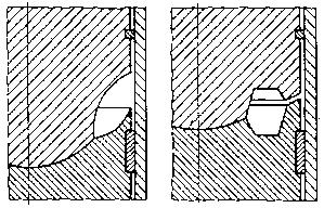
Much of the design of the Russian Diesel Hammers is derivative and unexceptional, as we saw in The Kinematics of Diesel Fuel Pump Cams. One major departure they did accomplish was the shape of the combustion chambers, as described in Diesel Hammers and illustrated at the right. Moving the combustion chamber inward, in reality, makes a great deal of sense, because it pulls the combustion chamber away from the immediate cooling effects of the cylinder wall. As Obert (1970) points out, “It should also be evident that heat losses are reduced by designing the combustion chamber to have a high volume to surface ratio.” This proved prophetic as the decade unrolled with the Mazda Wankel rotary engine, whose fuel efficiency was compromised by the large external surface of the combustion chamber. It should be noted that with compression ignition engines like the diesel hammer pulling the combustion chamber in also makes it possible to reduce losses due to radiant heat transfer.
But that’s not quite the rationale the Russians used to make this change. From Diesel Hammers:
Drop shaped combustion chambers on tubular diesel hammers as shown on the left hand side in Figure 4.11 were made in the USSR at the beginning and now outside as well, but it does not satisfy the driving parameters. During impact fuel is lifted at high speed around the anvil and pressed by centrifugal force to its surface. This reduces uniform fuel allocation in the combustion chamber. Except for the fact that such a combustion chamber does not promote for intensive air circulation during compression, it decreases thermal efficiency during expansion.
Today tubular diesel hammers made in the USSR used a toroidal shaped combustion chamber which makes possible fuel lifting around the sphere after its ejection from the fuel pump, influenced by the diameter d. This is shown on the right hand side of Figure 4.11. This makes for intensive air circulation.
As sort of a hat tip to the idea of reducing the area/volume ratio, there is evidence that the design began using a true toroid (circular cross-section) and only later went to the hexagonal cross-section shown in Figure 4.11. The difference between the two is illustrated below. Generally half of the cross-section was in the anvil and half in the ram so that the fuel, when impact atomisation took place, would be in the centre of the combustion chamber and the progress of the combustion would, in theory at least, start in the middle and progress outward to the walls. (The same concept, btw, applies to conventional combustion chamber, it just requires a smaller/steeper radius to make it happen.)

The true toroid is the diesel hammer counterpart to the “hemi-head” engine, so if you want a hemi head on the jobsite, such a hammer is the one for you. The probable reason they gravitated to the hexagonal cross-section is because it allows for a larger combustion chamber, which can be critical for the smaller hammers. All of the Russian hammers listed here and in subsequent posts will have a hexagonal cross-section combustion chamber unless otherwise noted.
Too Many Factories Complicate the Design
There’s a saying that “too many cooks spoil the broth,” and for the diesel hammers the complicated structure of the bureaucracy made matters worse. For a system which was supposed to be centralised and “command and control,” the way these hammers came to the jobsite was anything but straightforward.
The design work for the hammers was done by the research institute VNIIstroidormash, and then the manufacturing was done by separate organisations from the designers. There were four locations for these factories:
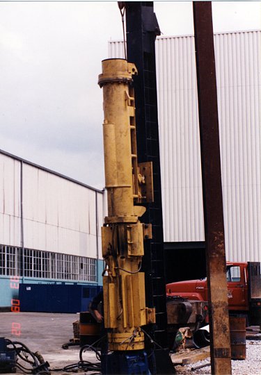
- Lyubertsy, southeast of Moscow, which Vulcan personnel visited in 1992 (see Russian Diesel Hammers at Vulcan: Series I and II.) Vulcan purchased the 2500 kg ram hammers from this organisation. The Lyubertsy hammers were the only hammers which retained the detachable catch groove assembly, which allowed this to be replaced without replacing the whole upper cylinder. A photo of this hammer is at the right, at Vulcan’s facility.
- Podolsk, south of Moscow, from which Vulcan purchased 1800 kg ram hammers.
- Bryansk, near the meeting of Russia, Belarus and Ukraine, which Vulcan personnel visited in 1994. Vulcan purchased 1250 kg ram hammers for this factory. Bryansk was a military plant, its quality was the best, although it, unique to the group, used the true toroidal combustion chamber. This visit was one for the ages, as documented in Half a Million Roubles. Is it Enough?.
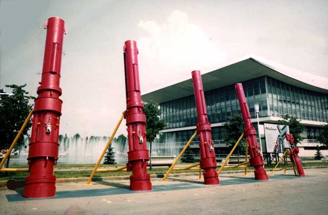
- Sterlitamak, in the Urals. The Russians had chosen this plant as their principal plant for hammers for export, and their original idea was to use this plant for Vulcan’s hammers. Unfortunately their business skills did not match their supposed prowess for manufacturing. Vulcan found this out the hard way, as documented in Russian Diesel Hammers at Vulcan: Series I and II. The “SP” series of diesel hammers is documented in Russian Diesel Hammers, and a photo of the lineup (including a rod-type hammer on the right) is shown below.
One additional problem with Sterlitamak’s hammers was that they were water cooled. We never got a straight answer as to why a country with a cold climate needed water cooled diesel hammers. They noted that the water reservoir was like a Russian samovar; the concept of the tea that might emerge is unappetising, to say the least.
All of this underscores the lack of uniformity in the overall configuration of Russian diesel hammers. Design changes done for one factory might be absent in another; the end users doubtless had their influence on what a hammer would look like.
Presenting the Data
The data can be summarised below, in the same format as before with the Nilens and Delmag hammers.
| Model | UR-2 (V12 Series I) | SP-75 | SP-76 | S-949B (V25 Series I) | S-954B |
| Factory | Bryansk (True Toroidal Combustion Chamber) | Sterlitmak/ Podolsk | Sterlitmak/ Podolsk | Lyubertsy | Lyubertsy |
| Ram mass, kg | 1250.0 | 1250.0 | 1800.0 | 2500 | 3500 |
| Compression volume, mm3 | 1316232 | 1311449 | 2274293 | 3160846 | 4516522 |
| Ratio of compression volume to ram mass, mm3/kg | 1053.0 | 1049.2 | 1263.5 | 1264.3 | 1290.4 |
| Cylinder diameter, mm | 300 | 300 | 345 | 400 | 470 |
| Cylinder cross-sectional area, mm2 | 70686 | 70686 | 93482 | 125664 | 173494 |
| Probable working stroke from drawings, mm | 313 | 280 | 310 | 410 | 382 |
| Actual expansion volume, mm3 | 23440898 | 21103483 | 31253718 | 54682966 | 70791404 |
| Ratio of Free Air Volume to ram mass, mm3/kg | 18753 | 16883 | 17363 | 21873 | 20226 |
| Actual compression ratio | 17.8 | 16.1 | 13.7 | 17.3 | 15.7 |
| Maximum Physical Stroke, m | 3.380 | 3.380 | 3.213 | 3.613 | 3.810 |
| Maximum Energy from Maximum Physical Stroke, kJ | 41.4 | 41.4 | 56.7 | 88.6 | 130.8 |
| Actual Working Volume, m3 | 0.0221 | 0.0198 | 0.0290 | 0.0515 | 0.0663 |
| Ratio of actual working stroke to cylinder diameter) | 1.04 | 0.93 | 0.90 | 1.03 | 0.81 |
| Initial Pressure (p1), MPa | 0.115 | 0.115 | 0.115 | 0.115 | 0.115 |
| Gas Constant k | 1.25 | 1.25 | 1.25 | 1.25 | 1.25 |
| Compression Pressure (p2), MPa | 4.207 | 3.706 | 3.043 | 4.058 | 3.586 |
| Maximum Combustion Pressure (p3), MPa | 10.00 | 10.00 | 10.00 | 10.00 | 10.00 |
| Ratio of Combustion Pressure to Compression Pressure | 2.38 | 2.70 | 3.29 | 2.46 | 2.79 |
| Total Thermodynamic Energy, kJ | 15.652 | 16.531 | 30.419 | 38.293 | 57.635 |
| Ratio of Thermodynamic Energy to Maximum Stroke Energy | 37.76% | 39.88% | 53.62% | 43.22% | 44.06% |
| Mean Effective Pressure from Energy and Actual Working Volume, kPa | 707.451 | 835.238 | 1049.675 | 743.239 | 869.629 |
Some notes are as follows:
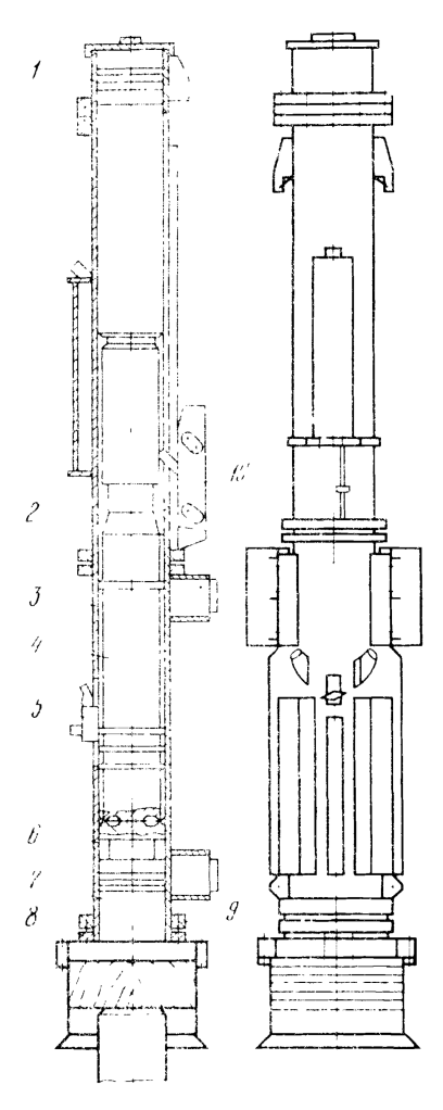
- The S-949B (which became the V25 Series I) is shown at the right. The S-954B is a similar technology with the detachable catch groove assembly. This feature was abandoned both by the “SP” Sterlitamak hammers and the Bryansk hammers. The specs for these two hammers can be seen in Diesel Hammers.
- Contrary to the original scheme, the compression ratio varies considerably across the range shown here. The closest hammer to the “standard” (15) is the S-954B.
- The only hammer whose themodynamic energy is more than half of its “catch ring energy” is the SP-76; it also has the highest mean effective pressure of the group, the others around 800 kPa.
- The “SP” series hammers originally had a split lower cylinder just below the exhaust ports (the SP-76 with this feature is shown at the top of the page.) This predictably did not work, something described in Russian Diesel Hammers. My guess is that they were trying to effect precision boring with a shorter bore but, as Vulcan knew all too well, this had problems of its own.
- All of the hammers were analysed using the 10 MPa maximum combustion pressure. Vulcan never ran tests to determine the maximum combustion pressure of these hammers.
References Not Hyperlinked
Obert, E.F. (1970) Internal Combustion Engines. Third Edition. Scranton, PA: International Textbook Company


2 thoughts on “Diesel Hammers: The Russian Hammers and Hemi-Headed Pile Drivers”