

In Diesel Hammers: Some Basic Thermodynamics, and the Mean Effective Pressure it was noted that the diesel hammers were developed in Germany between the World Wars. The Germans went to war the second time with diesel hammers in hand to aid their war effort. (The U.S. did so with air/steam and drop hammers, many of which Vulcan made.) With the end of the war, the technology of diesel pile hammers fell into Allied hands and was distributed to those who wanted to develop it.
In the U.S., the most famous of those recipients was Syntron, eventually bought out by the crane manufacturer Link-Belt. As noted in Beginnings of Diesel Hammers, and the Vulcan IC-65:
The Syntron concern was the first to actually manufacture a commercially viable diesel hammer. They made two major changes to the Delmag concept: a) they added engine-style atomised fuel injection and b) they included a dashpot type bounce chamber in the top to increase the blow rate. The result was a hammer which was a diesel hammer but had the blow rate comparable to air/steam hammers, which resulted in faster pile installation.
The Syntron hammer was acquired by Link-Belt, which manufactured it until the late 1970’s, after which the product line was acquired and subsequently expanded by International Construction Equipment.
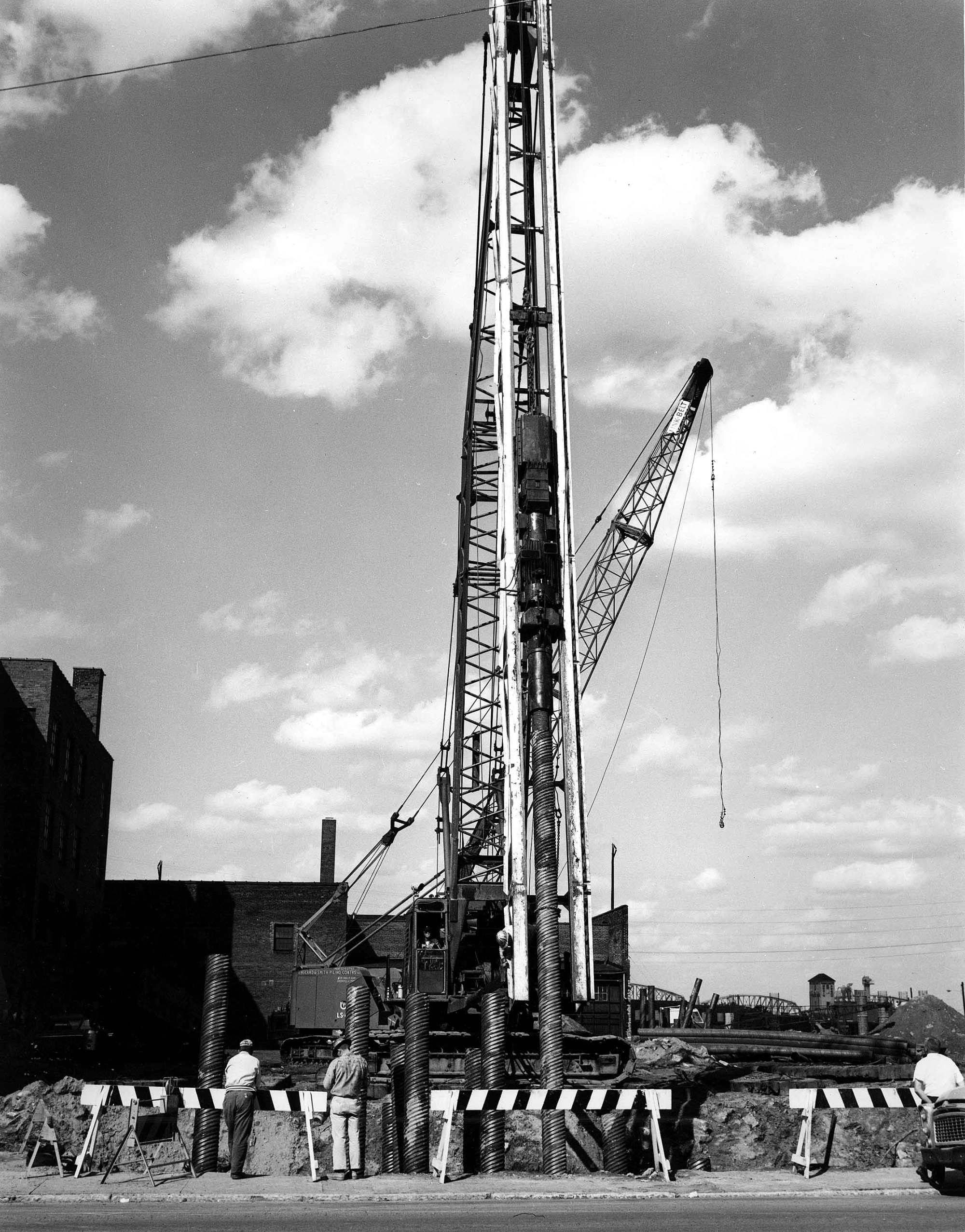
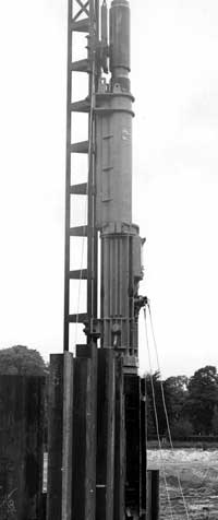
In addition to being expensive (and sometimes difficult) to produce, the hammer shifted the energy-ram weight ratio more in the direction of Vulcan’s hammers, which made it heavier and negated one of the advantages of the Delmag concept: light weight. An example of the Link-Belt hammer is shown at the top, along with another of Vulcan’s non-hammer products, the Vulcan Expanding Mandrel. More information can be found on this hammer in Leigh (1964).
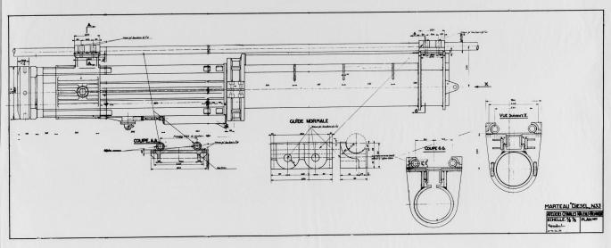
A manufacturer that took a more conventional approach to using the Delmag technology was the Belgian manufacturer Nilens, which developed a series of three hammers. The Nilens hammers were mounted in front of the leaders (as were the Delmag hammers and most European diesels) and were frequently used with dedicated piling rigs long before these were a thing for American contractors. There were two significant changes in the hammer design: the fuel pump was different from its Delmag counterpart, and the starting device was adapted to be integral to the hammer before Delmag opted to do so. It was a conservative adaptation and one that resulted in a hammer that ran well as long as the parts were all made to spec.
Objectives and Outline of the Analysis
Now we get to the goal of the series: developing an analysis method for diesel hammer performance with the following objectives:
- Determining the thermodynamic output of a diesel hammer according to Equation (7) of Diesel Hammers: Some Basic Thermodynamics, and the Mean Effective Pressure. This can be for either existing or anticipated hammer designs. In this phase of the analysis, we’ll use some older hammers from Delmag and Nilens.
- Comparing that output with the maximum physical stroke possible for a given hammer.
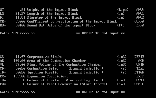
To accomplish this, we need to look at Equation (7) and concentrate on its parameters. These are listed again, with some explanation:
atmospheric pressure (or close to it.) Generally WEAP and its progeny assume this to be the atmospheric pressure at sea level, but there are other ways to do this, as we will see.
maximum combustion pressure. The WEAP86/87 manual warns that “…the maximum pressure, pmax, should be determined by measurement.” Between the complexities of combustion and turbulence and the problems with the anvil moving out from under the combustion chamber, doing this using any kind of combustion theory is difficult. If the hammer is in their database–and we’ll use the WEAP87 database for the earlier Delmags–the maximum pressure is in the database. To apply this knowledge to hammers with different compression ratios (and thus different compression pressures,) we assume an ideal gas in a constant volume process, and thus the ratio of the pressures (and temperatures for that matter) will be the same for similar hammers. This will be subject to modification for later stages.)
compression ratio, see Equation (3). The compression ratio for hammers in the WEAP databases can be determined easily. For hammers where we’re working from drawings, take a look at the centre view of the cycle below. At what point does the ram close the exhaust ports? For the purposes of our study we will use the point where the bottom piston ring passes the bottom of the lowest exhaust ports (Nilens had an array of them, other hammers have only one set.)
ideal gas constant, see Equation (4). For this phase of the analysis, we will use the WEAP86 value of 1.35; this will change for the later hammers.
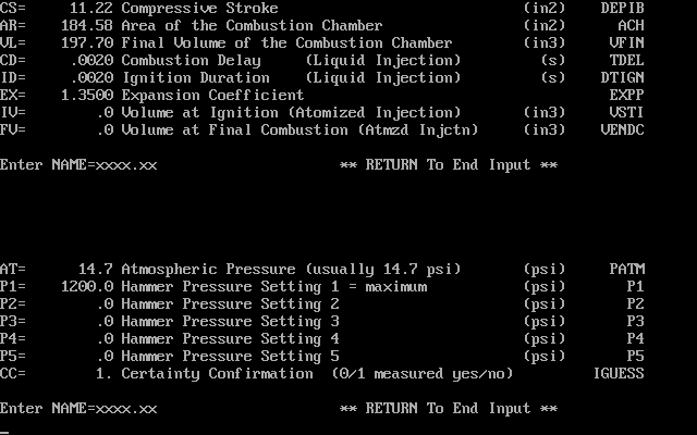
compression volume, see Equation (1). This is the volume trapped between the ram and anvil at impact (see the rightmost view below.) For the Delmag hammers, this is given in the WEAP database; for the Nilens hammers, it is computed from the drawings.
As noted, the Delmag data is taken from the WEAP87 database; the hammers used and their data is shown below.

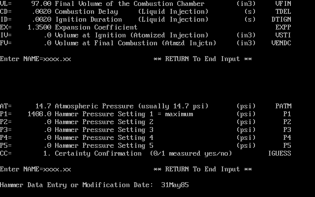
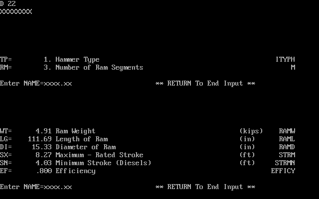

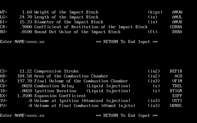
The data for the Nilens hammers was taken from the drawings which Vulcan had accumulated during the course of their relationship with Nilens. Three hammers were analysed: the N33, N46 and N60, whose basic specifications will be shown.
With all of this we can view the results of the study.
| Model | Delmag D-12 | N-33 | N-46 | Delmag D-22 | N-60 |
| Ram mass, kg | 1250 | 1250.0 | 1800.0 | 2200.0 | 2400.0 |
Compression volume  , mm3 , mm3 | 1590800 | 1796991 | 2407245 | 3242280 | 3066980 |
| Ratio of compression volume to ram mass, mm3/kg | 1272.6 | 1437.6 | 1337.4 | 1473.8 | 1277.9 |
| Cylinder diameter, mm | 300 | 300 | 355 | 390 | 410 |
| Cylinder cross-sectional area, mm2 | 70686 | 70686 | 98980 | 119459 | 132025 |
| Working stroke from drawings or database, mm | 297 | 310 | 305 | 285 | 300 |
| Actual expansion volume, mm3 | 22597216 | 23709600 | 32596085 | 37288112 | 42674609 |
| Ratio of Free Air Volume to ram mass, mm3/kg | 18078 | 18968 | 18109 | 16949 | 17781 |
Actual compression ratio  | 14.2 | 13.2 | 13.5 | 11.5 | 13.9 |
| Maximum Physical Stroke, m | 2.616 | 2.930 | 2.930 | 2.521 | 2.930 |
| Maximum Energy from Maximum Physical Stroke, kJ | 32.1 | 35.9 | 51.7 | 54.4 | 69.0 |
| Actual Working Volume, m3 | 0.0210 | 0.0219 | 0.0302 | 0.0340 | 0.0396 |
| Ratio of actual working stroke to cylinder diameter | 0.99 | 1.03 | 0.86 | 0.73 | 0.73 |
| Initial Pressure (p1), MPa | 0.101 | 0.107 | 0.107 | 0.101 | 0.107 |
| Gas Constant k | 1.35 | 1.35 | 1.35 | 1.35 | 1.35 |
| Compression Pressure (p2), MPa | 3.632 | 3.483 | 3.607 | 2.731 | 3.742 |
| Maximum Combustion Pressure (p3), MPa | 9.65 | 9.05 | 9.38 | 8.27 | 9.73 |
| Ratio of Combustion Pressure to Compression Pressure | 2.66 | 2.60 | 2.60 | 3.03 | 2.60 |
| Total Thermodynamic Energy, kJ | 16.555 | 17.011 | 23.745 | 29.507 | 31.585 |
| Ratio of Thermodynamic Energy to Maximum Stroke Energy | 51.61% | 47.35% | 45.90% | 54.24% | 45.79% |
| Mean Effective Pressure from Energy and Actual Working Volume, kPa | 788.101 | 776.308 | 786.565 | 1033.267 | 797.435 |
Some additional explanation of the parameters (in addition to the earlier one of the variables) is in order.
- The “ratio of compression volume to ram mass” and the “ratio of Free Air Volume to ram mass” are measures of the configuration of the combustion area relative to the mass of the ram. The higher these ratios, the more thermodynamic energy is possible for the ram.
- The maximum physical stroke is the stroke the ram experiences from the standard impact point to when the catch ring hits the catch ring groove. The maximum stroke energy is simply that physical stroke multiplied by the ram weight in kN.
- The initial pressure for the Nilens hammers is based on the post Diesel Hammers, and is based on two ideas: a) there is backpressure during the downstroke which makes the pressure in the cylinder higher than atmospheric even before compression, and b) that backpressure depends upon the combustion chamber configuration.
- The pressure ratio
is assumed to be 2.6, or comparable to the Delmag hammers.
Now for some observations on the results:
- The ratio of the thermodynamic energy to the “catch ring energy” for the Delmags ranges in the low to medium 50% range, while the Nilens hammers vary around the mid-40% range. Part of this may be due to the fact that the maximum physical stroke of the Nilens hammers is higher than the Delmags. In all cases, however, to hit the catch ring groove it is necessary to have nearly as much rebound energy from the pile as thermodynamic energy from the combustion.
- The Nilens compression ratio is consistent, indicating that they were designed in one effort, while that of the Delmags is not.
- The mean effective pressure of all of the hammers is consistent except for the D-22.
References Not Hyperlinked
Leigh, T.M. (1964) “The Self-Contained Diesel Pile Hammer.” Society of Automotive Engineers, National Farm, Construction and Industrial Machinery Meeting, Milwaukee, Wisconsin, September 14-17, 1964, pp. 1-9


3 thoughts on “Diesel Hammers: Delmag, Nilens and the Method of Analysis”