

This is an overview of the motion of the “standard” type of diesel fuel pump cam which is used to deliver fuel from the fuel tank to the combustion chamber of a single-acting, tubular type of diesel hammer.
What are Kinematics?
As defined in Seely and Ensign, “Kinematics deals with the relation between distance, time, velocity, and acceleration.” It only considers the basics of the motion itself, not the effects of that motion or how to predict it for particles/bodies which are not constrained. To keep things simple for everyone, we’ll present the solution graphically. My guess is that, when the Germans came up with the design back before World War II, they did it that way, as was the custom of the day.
The Basics of the Problem
The fuel pump set-up is shown at the top of the article. In the upper right hand corner is the ram, which moves downward. The cam (1) is stationary until the ram strikes it and moves it to the right, or more precisely rotates it counterclockwise. As this is accomplished the cam pushes down the plunger (2), which in turn pushes fuel through the lower valve (7) and into the combustion chamber, subject to the flow control mechanism (5).
Our goal is to estimate the motion of the cam (1) and the plunger (2) as the ram moves downward. While the ram and plunger are in pure translation (straight line motion,) the cam is in pure rotation. Although the interaction between the cam on the one hand and the ram and the plunger is a little complicated, the fact that none of the parts mix translation and rotation makes the analysis simpler.
The Hammer and Cam for Analysis
Getting drawings even for something as “generic” as most diesel hammers in the U.S. these days can be difficult; American manufacturers and distributors have always been secretive even when the technology is old. It should be evident to most people in the industry that the cam looks a lot like what’s in most diesel hammers today and has been for a long time. To bridge the gap I’ll use the Russian drawings I have on hand and specifically those of the SP-76, which is described in the article Russian Diesel Hammers. A photo of this machine is shown below.

The specifications are there but in brief this hammer has an 1800 kg ram and conventional tubular construction. When Vulcan commissioned its diesel hammer drawings the ram weight was kicked up to 1900 kg to be more comparable to those already on the market; the differences are few.
Based on what we have the cam design dates back to the S-995A, specifications for which are described in Diesel Hammers. What this tells me is that the Russians copied this design from Delmag to start with and made few (if any) changes after that. Inspection of the specs will also show that the S-995A is a 1250 kg ram hammer, which means that the same cam can be used in two sizes of hammers, always advantageous for end user and manufacturer alike. As we will see, this was a wise decision.
Next let us consider the diagram below. The profile of the cam was redrawn from the original (resolving a few ambiguities along the way) and some essential dimensions have been added.
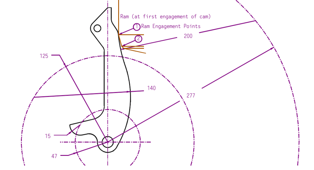
The ram is shown at the first engagement of the cam and the cam is in the upright position. Point 1 is the upper ram engagement point; it is where the diameter of the ram breaks away into a 15 degree chamfer which ends with Point 2, the lower ram engagement point. This in turn goes to another, 45 degree chamfer which does not contact the ram. The actual contact between the ram and the cam takes place at one of three places; a) at the ram engagement point 1, b) along the 15 degree chamfer, especially for the lower (140 mm) radius, and c) at the ram engagement point 2. At certain points both ram engagement points contact the cam; these are transitional points, although there are others.
It was noted earlier that the cam is in pure rotation. This means that every point on the cam–and those outside of it which define its geometry–are also in pure rotation. There are two critical radii along the front of the cam which faces the ram: the concave 200 mm radius just below where the ram makes first contact, and the convex 140 mm radius where most of the contact between the ram and the cam takes place. Both of these radii have centres which rotate, and their rotational tracks are noted in the drawing above. The ram outline was lowered progressively and the cam’s counterclockwise rotation was noted and the results recorded at the transition points. No attempt was made at a rigourous, continuous analysis of the cam’s motion.
There is also another radius of importance, namely that of the plunger contact arm. Its 15 mm radius track is also noted.
Breaking Down the Motion
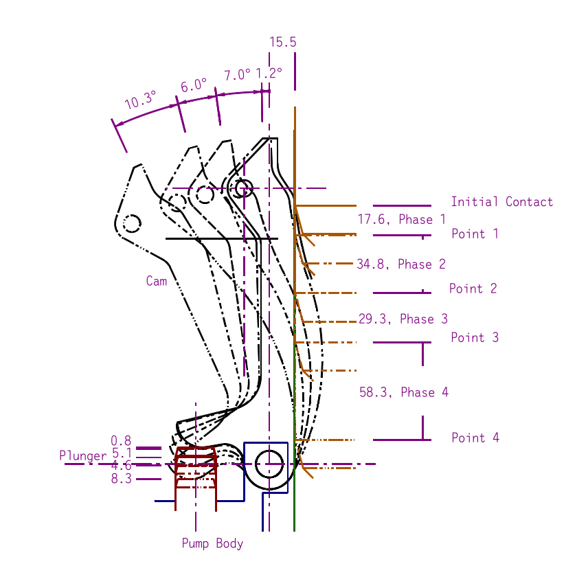
Below is a step-by-step breakdown of the cam’s motion through the four phases of its contact with the ram.
There are a few assumptions made about this analysis:
- The ram’s velocity is assumed constant throughout its contact with the cam. Analysis of the drawings showed that the distance from the upper piston ring’s contact with the lower catch ring to where initial contact is made with the cam is 2213 mm, which for 90% efficiency means that the velocity at first contact is 6.25 m/sec. After the 140 mm of ram movement which rotates the cam to its final position, that velocity increases to 6.45 m/sec. This is an increase of 3.2%, which justifies the constant velocity assumption, especially if we use an average velocity of 6.35 m/sec.
- No wear on the ram is assumed; it is reasonable to assume that, as the ram wears, the two ram engagement points on the ram will wear also.
- The ram is assumed to be centred in the cylinder.
With that, there are four phases of contact between the ram and the cam:
- From initial contact to Point 1, only engagement point 1 contacts the 200 mm radius.
- At Point 1, both engagement points contact the cam, but from there only Point 2 does so in the 200 mm radius.
- The chamfer between the two engagement points are tangent to the 140 mm radius and the contact point moves up the chamfer.
- Engagement point 1 is the only contact that the ram has with the 140 mm radius of the cam; this is the single longest phase until the full rotation of the cam is achieved and the ram’s straight side holds the cam back in place until upstroke reverses the process and the cam rotates clockwise to its original position.
Putting this all together, the following are the results in tabular form of the motion study at the “break points” of the motion study.
| End of Phase | Ram Drop During Phase, mm | Angle of Rotation, Degrees | Ratio of Rotation to Ram Movement, deg/mm | Plunger Movement During Phase, mm | Ratio of Rotation to Plunger Movement, deg/mm | Time of Phase, msec | Average Rotational Speed of Cam During Phase,deg/msec | Average Speed of Plunger during phase, mm/msec | Average Rotational Speed of Cam During Phase, RPM |
| 1 | 17.6 | 1.2 | 0.068 | 0.8 | 1.5 | 2.77 | 0.43 | 0.29 | 72.2 |
| 2 | 34.8 | 7 | 0.201 | 5.1 | 1.4 | 5.48 | 1.28 | 0.93 | 212.9 |
| 3 | 29.3 | 6 | 0.205 | 4.6 | 1.3 | 4.62 | 1.30 | 1.00 | 216.5 |
| 4 | 58.3 | 10.3 | 0.177 | 8.3 | 1.2 | 9.19 | 1.12 | 0.90 | 186.8 |
| Total | 140.0 | 24.5 | 0.175 | 18.8 | 1.3 | 22.06 | 1.11 | 0.85 | 185.1 |
From the tabulated results we can note the following:
- Once the cam “comes up to speed” during the first phase, its rotational speed–and the relationship between the ram movement and the cam movement–is reasonably constant. This means that the cam accelerations are minimised, which will result in a longer life in what is, like so many pile driving applications, a demanding one.
- The plunger velocity shows a similar trend, which will result in a steady fuel flow out of the pump. (The SP-76 is different than the construction at the top of the post in that the nozzle to the combustion chamber is physically separate from the fuel pump.)
- Note the way the tangent point of the cam moves across the face of the plunger during cam and plunger motion, which requires a plunger which is large enough and laterally supported sufficiently to withstand the action of the cam.
- The nominal stroke of the cam is 16 mm, which is smaller than the stroke indicated by the geometry of 18.8 mm. This is necessary to compensate for wear and other variations in the configuration of the fuel pump and cam.
Although redesign of such a component is unlikely, analyses such as this are interesting in that they show us the principles that went into the design to start with.


One thought on “The Kinematics of Diesel Fuel Pump Cams”