

The most common machines for driving piles are diesel hammers, the main advantages of which are: independence from external energy sources (autonomy), high productivity, simplicity and ease of operation, and low cost of manufacture. The classification and main parameters of diesel hammers are given in GOST 7888-80.
All existing and currently used diesel hammers can be divided into two groups: by the nature of the movement of the striking part – diesel hammers with a free fall of the striking part and diesel hammers with forced movement of the striking part downwards (high-speed diesel hammers); by the design solution of the guides for the movement of the striking part – tubular and rod.
The main types of diesel hammers that have found the widest application are rod and tubular diesel hammers with a free fall of the striking part. The first are characterized by a high compression ratio (~ 30) and fuel sawing using a high-pressure pump and injector, the second – by a lower compression ratio (14-16), the presence of a low-pressure pump that supplies unatomized fuel to the combustion chamber and impact sawing of the fuel.
Rod diesel hammers are used in some specific pile driving conditions characterized by the presence of weak soils at the construction site.
Since the designs and calculation principles of rod diesel hammers have been sufficiently covered in a number of works, only the technical characteristics of two modernized rod diesel hammers, serially produced by our industry, are given here (Table 4.3).
| Parameter | SP-60 (DM-240) | SP-6B (S-330B) |
| Mass of striking part, kg | 240 | 2500 |
| Maximum striking energy, kJ | 3 | 58.8 |
| Maximum stroke, m | 1.3 | 2.4 |
| Blows per minute | 57 | 50 |
| Weight of driven piles, kg | 300-500 | 1200-3200 |
| Width of Guides, mm | – | 360 |
| Hammer height (without driving accessory,) mm | 1981 | 4520 |
| Hammer mass (with crab,) kg | 350 | 4220 |
The most widespread are tubular diesel hammers, which have a number of advantages over rod diesel hammers, and, in particular, greater efficiency [8].
In the USSR, a standard series of tubular diesel hammers with striking parts weighing from 500 to 5000 kg are currently produced. These diesel hammers are produced in two modifications with water (Table 4.4) and air (Table 4.5) cooling and are manufactured according to a single fundamental and design scheme.
| Parameter | S-995A (SP-40A) | S-996A (SP-41A) | S-1047A (SP-47A) | S-1048A (SP-48A) | SP-54-1 |
| Mass of striking parts, kg | 1250 | 1800 | 2500 | 3500 | 5000 |
| Maximum impact energy, kJ | 22 | 31.4 | 42.7 | 59.8 | 88.3 |
| Blows per minute | 43-55 | ||||
| Width of Guides, mm | 360 | 360 | 360/625 | 625 | 625 |
| Hammer height (without driving accessory,) mm | 3955 | 4190 | 4970 | 5080 | 5500 |
| Hammer mass, kg | 2600 | 3500 | 5600 | 8000 | 10000 |
| Parameter | S-859A | S-949A | S-954A | S-977A |
| Mass of striking parts, kg | 1800 | 2500 | 3500 | 5000 |
| Maximum impact energy, kJ | 31.4 | 42.7 | 59.8 | 88.3 |
| Blows per minute | 42 | 42 | 42 | 55 |
| Width of Guides, mm | 360 | 360/625 | 625 | 625 |
| Hammer height (without driving accessory,) mm | 4165 | 4685 | 4800 | 5520 |
| Hammer mass, kg | 3500 | 5800 | 7300 | 9000 |
Notes to Tables 4.4 and 4.5:
- Maximum stroke of the ram is 3 m.
- Compression ratio = 15.
- The diesel hammers C-1047A (SP-47A) and S-949A have a guide width of 360 mm when working with a light pile rig and a 625 mm width when working with a heavy pile rig.
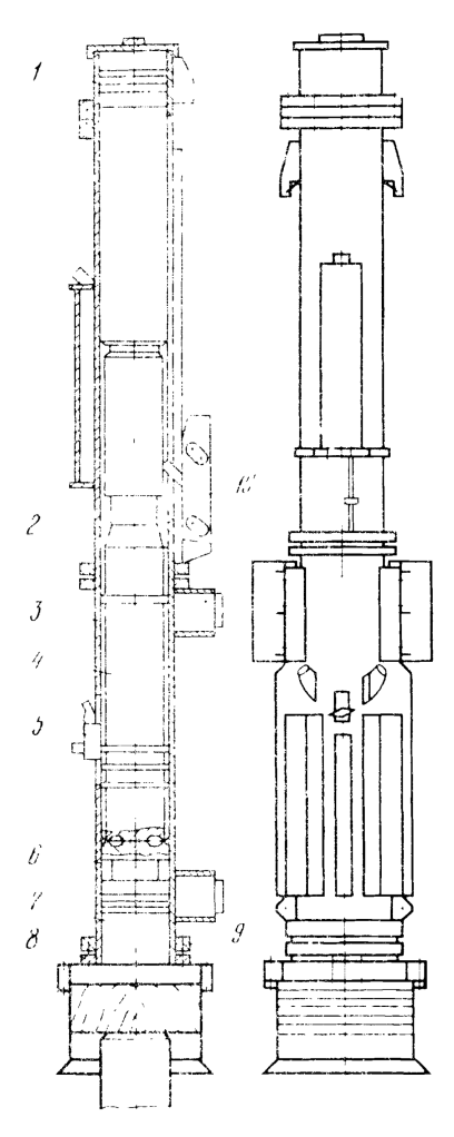
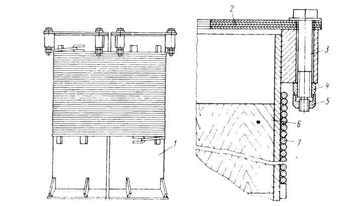
The S-954B tubular diesel hammer with air cooling (Fig. 4.6) (like all models of diesel hammers) can operate in a set with a pile driver of the appropriate lifting capacity at an ambient temperature of down to -30° C without preheating, as well as with a pile settlement of up to 150 mm per blow [16].
Figure 4.6 Tubular diesel hammer S-949B with air cooling
The diesel hammer consists of the following main units and parts:
- Catch ring assembly
- Guide pipe (upper cylinder)
- Cylinder (lower cylinder
- Piston/Ram
- Fuel Pump
- Upper semirings
- Anvil
- Shock absorber ring
- Lower semirings
- Crab (starting device)
Guide pipe 2 is connected to cylinder 3 with bolts. Anvil 7 is installed in cylinder 3 with the help of upper semirings 6, located at the anvil point, and lower semirings 9, secured in the cylinder with shock absorber ring 8 and bolts. Piston 4 of the diesel hammer is made of a steel forging. The lower end of the piston is spherical with an end groove, which, when in contact with the spherical part of anvil 7 (which also has an end groove), forms a combustion chamber. The piston in the cylinder is sealed with four compression rings. To prevent the piston from jumping out in case of excessive bounce, catch rings are installed on it, which holds the piston in the annular grooves of the catch rings 1.
The anvil 7 is also made of a steel forging with a spherical recess and an end groove in the upper part. The anvil seal in the cylinder is provided by four compression rings. The shock absorber, installed between the ring and the lower widened part of the anvil, serves to soften the impact of the cylinder on the anvil. On the guide pipe 2 there is an oil tank, from which the lubricant is supplied through an annular groove to the surface of the guide pipe and through an oil pipeline to the area of the compression rings on the anvil. The lubricant is supplied to the specified units in portions with each blow of the diesel hammer thanks to a special inertial valve located in the oil tank.
The low-pressure fuel pump used in tubular diesel hammers (Fig. 4.7) consists of the following:
- Lever
- Plunger
- Bushing
- Housing
- Adjusting lever
- Return Spring
- Ball
- Ball spring
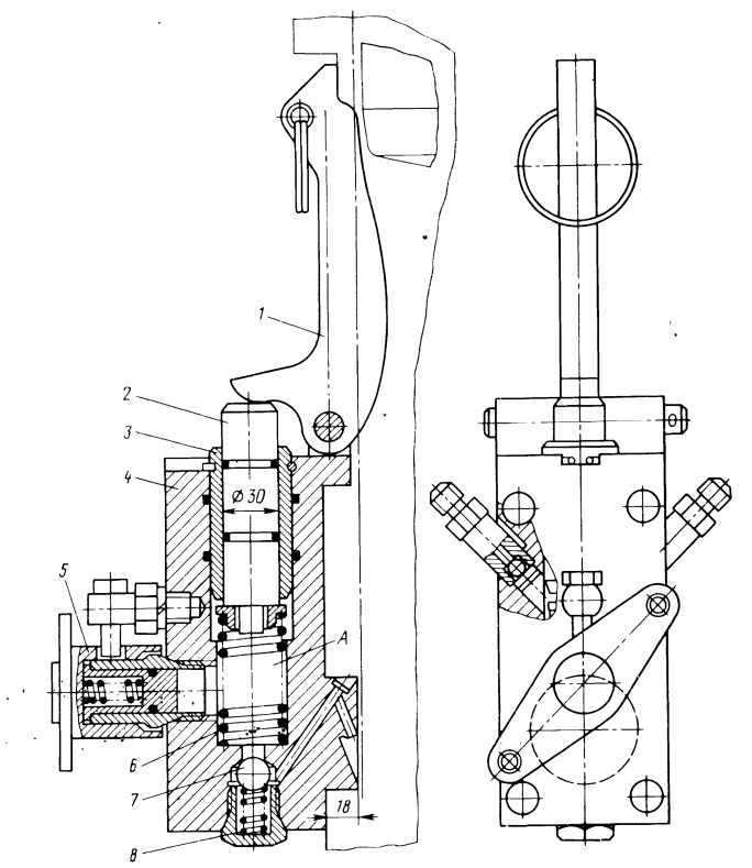
The cylindrical projection of the housing 4 with a nozzle hole enters the recess of the diesel hammer cylinder and directs the fuel stream to the center of the anvil. The housing contains: bushing 3, return spring 6 and plunger 2. Lever 1 is installed in the lugs of housing 4; a valve with a ball 7 and spring 8 is installed in the lower part of the housing. When fuel is supplied by the pump, the valve opens and blocks the access of gas to the pump cavity. When turning the adjusting lever 5 clockwise, the amount of fuel supplied to the combustion chamber decreases, counterclockwise – increases. The adjusting lever rotates with the help of two ropes attached to the holes of the lever.
The starting device – “crab” (Fig.4.8) consists of the following:
- Cheek
- Pin
- Cheek Finger
- Control Cable
- Cheek Projection
- Lifting Tooth Finger
- Lifting Tooth Rod
- Lifting Tooth Rod
- Splined Shaft
- Spring
- Finger
- Housing
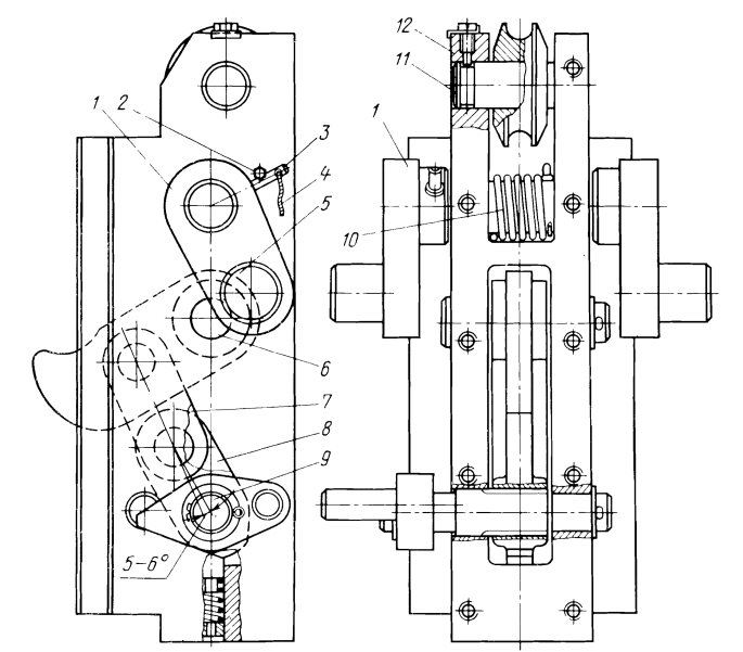
A lifting tooth is installed on the axis of the housing 12, connected by hinged rods 7 and 8 with a splined shaft 9, on which a cam is installed, engaging with the end projection with the cam of the splined shaft. On the cam there is an eccentrically located finger, which serves to rotate the splined shaft 9 counterclockwise during the lowering of the cat and the cocking of the lifting tooth. In the lower part of the housing 12, a lock is installed for fixing the splined shaft 9 in two extreme positions. The rod 8 rests against the finger 6 when the lifting tooth is cocked, making an offset of 5-6° with the rod 7. In the upper part of the housing 12, an eye is installed on the finger 11, to which the rope of the pile driver winch is attached. The “crab” moves along the guides located directly on the hammer.
Water-cooled diesel hammers are similar in design to air-cooled diesel hammers and differ from the latter by the presence of a water tank. The tank is located in the combustion chamber area and consists of three vertical sections that have openings at the top that communicate with the atmosphere. When the hammer is operating, the water, heating up in the tank, begins to circulate through the vertical pipes, uniformly heating the cylinder.
In recent years, so-called high-speed tubular diesel hammers have been increasingly used in construction practice, in which the downward movement of the striking part is accelerated by introducing a pneumatic buffer into the design. The buffer reduces the stroke of the striking part, which allows increasing the frequency of impacts with constant energy of a single impact and, consequently, increasing the effective power of the diesel hammer and its productivity. As a rule, the frequency of impacts of a high-speed hammer is selected based on the fact that the reactive force acting upward on the hammer body should not exceed the weight of its non-moving parts. In practice, the frequency of impacts of high-speed diesel hammers is within 60-70 impacts per minute.
All diesel hammers, the technical characteristics of which are given in Tables 4.6 and 4.7, are made according to a single design scheme and differ only in weight, dimensions and cooling method.
| Parameter | SO1-133 | URB-500 | URB-1250 |
| Mass of striking part, kg | 350 | 500 | 1250 |
| Maximum impact energy, kJ | 5.5 | 8.3 | 18.6 |
| Maximum stroke, m | 1.6 | 1.8 | 1.9 |
| Blows per minute | 60 | 75 | 60 |
| Hammer height, mm | 2860 | 3350 | 3750 |
| Hammer mass, kg | 650 | 1200 | 2600 |
| Parameter | URB-1800 | URB-2500 |
| Mass of striking part, kg | 1800 | 2500 |
| Maximum impact energy, kJ | 26.5 | 28.5 |
| Maximum stroke, m | 1.9 | 1.9 |
| Blows per minute | 60 | 60 |
| Hammer height, mm | 4030 | 4900 |
| Hammer mass, kg | 4000 | 6000 |
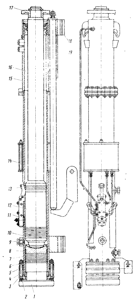
The air-cooled diesel hammer (Fig. 4.9) with a striking part weighing 1250 kg consists of the following:
- Anvil
- Shock Absorber
- Lower Anvil Flange
- Anvil Retaining Bolt
- Shock Absorber
- Upper Anvil Flange
- Lower (working) cylinder
- Anvil centralising semiring
- Compression plug
- Piston rings
- Fuel pump
- Piston (ram)
- Upper piston rings
- Fuel tank
- Upper cylinder (guide pipe)
- Bounce chamber
- Piston flange
- Diesel hammer grips
- Lifting pipe
The upper cylinder 15 is connected to the lower (working) cylinder 7. In the internal cavity of which the striking part (piston) 12 and anvil 1 are located, there is a lifting rod 19 and a crab (not shown in the figure). A flange 17 is attached to the upper part of the piston. The anvil is connected to the flange of the working cylinder by means of two shock absorbers 2 and 5. A fuel pump 11 is fixed on the working cylinder, in which a second pumping chamber is made, which allows lubricant to be supplied through oil lines to the area of the anvil bearing and the upper bearing fixing the piston tail. The small diameter of the piston passes through the bearing fixed in the guide cylinder. The diesel hammer is connected to the pile driver guides by two pairs of grips 18. The hammer is started by a crab interacting with a lifting rod, which in turn interacts with the piston flange 17.
The diesel hammer operates as follows. The crab grabs the rod by the lower end and lifts it until it stops against the piston flange. The striking part rises to the starting height and is dropped. The rod falls to its original position, the piston activates the fuel-lubricating pump, compresses the air in the working cylinder and cuts the fuel in the combustion chamber with a blow. After the fuel has burned, the piston, when moving upward, compresses the air in the pneumatic buffer 16, formed by the internal cavity of the guide pipe and the piston small diameter. The air in the pneumatic buffer is compressed and accumulates part of the expansion work obtained in the working cylinder during fuel combustion.
After the piston reaches top dead center, the air begins to expand and creates additional acceleration as the piston moves downward.
The pneumatic buffer of the diesel hammer is equipped with two valves, one of which is designed for a certain pressure in the pneumatic buffer and releases air, preventing the hammer body from jumping up, the other compensates for air leaks from the pneumatic buffer during expansion. The working cylinder is provided with longitudinal cooling ribs. The design of diesel hammers with a striking part weighing 350 and 500 kg differs from that described above only in that the cooling ribs of the working cylinder are made in the form of annular protrusions as a single unit with the cylinder.
Since tubular diesel hammers have a high impact energy, they are all equipped with special devices – caps, installed between the anvil and the upper end of the pile being driven, ensuring uniform distribution of the impact load along the end of the pile and protecting the pile from destruction during driving [9].
Currently, two types of caps are used: cast hammer-type and light with an elastic band.
Having high reliability and durability, cast caps, however, are not free from disadvantages, the main one of which is the significant mass of the cap. This circumstance (in addition to increased metal consumption) somewhat reduces the immersion capacity of the diesel hammer, since an additional mass of the cap (400-500 kg) is added to the mass of the pile being driven, thereby worsening the ratio between the mass of the striking part and the mass of the pile being driven.
At present, a number of tubular diesel hammers of the Sterlitamak plant “Stroimash” are equipped with light heads, the diagram of one of which is shown in Fig. 4.10, with components as follows:
- Housing
- Semirings
- Retaining bolt
- Retaining nut
- Retaining lock nut
- Hardwood cushion
- Flexible band
The headgear consists of a housing 1 connected by means of a set of detachable half rings 2 to the flange of the diesel hammer anvil. A wooden shock absorber 6 is installed inside the housing. The round housing 1 has a longitudinal section regulating the transfer of dynamic loads to the housing that occur when the shock absorber is deformed at the moment of impact. On the outside, the housing is covered with a flexible band 7 made of wire, the ends of which are fixed to the housing of the headgear. Half rings 2 are connected to the housing by means of bolts 3, nuts 4 and lock nuts 5, which have conical surfaces for better locking. The shock absorber 6 of the headgear is made of hardwood, and for greater durability, wooden beams are installed on the knotweed so that the impact is transmitted along the fibers. Since heads with a flexible bandage, unlike cast heads, perceive the impact load, absorbing it with elastic deformations of the light split body and the wire that holds it together, the weight of such a head for the heaviest diesel hammer does not exceed 200 kg.
Abroad, diesel hammers are produced in Great Britain, the USA, Germany, the Netherlands and Japan (in these countries, only tubular diesel hammers are produced.)
The general trend for all foreign companies without exception that produce diesel hammers is the expansion of the production of tubular (and especially heavy) diesel hammers while simultaneously reducing the production of rod diesel hammers, as well as a gradual transition to the production of high-speed diesel hammers.
In Great Britain, tubular diesel hammers are manufactured by British Steel Piling (BSP) (Table 4.8), which until 1976 produced three models (DE-20, DE-30 and DE-40) and is expanding its program by producing DE-30V and DE-50V diesel hammers. Diesel hammers of this company can be used with pile drivers or mounted on a crane.
Table 4.8 Technical characteristics of BSP tubular diesel hammers
| Parameter | DE-20 | DE-30 | DE-30V | DE-40 | DE-50V |
| Mass of striking part, kg | 907 | 1270 | 1360 | 1814 | 2260 |
| Maximum impact energy, kJ | 21.7 | 30.4 | 36.6 | 43.5 | 61 |
| Blows per minute | 48 | 48 | 47 | 48 | 47 |
| Hammer mass, kg | 2445 | 3685 | 3457 (without driving accessory) | 4481 | 4685 (without driving accessory) |
The latest models of BSP diesel hammers have a specially designed anvil (with a heel corresponding to the profile of the sheet pile being driven), which eliminates the need to use a cap
To increase the productivity of piling operations, BSP has created high-speed diesel hammers (Table 4.9) with an increased impact frequency.
Table 4.9 Technical characteristics of high-speed tubular diesel hammers from BSP
| Parameter | DA-35V | V-15 | V-45 |
| Mass of striking part, kg | 1270 | 1500 | 4500 |
| Maximum impact energy, kJ | 37.7 | 35.6 | 107 |
| Blows per minute | 72 | 80-100 | 80-100 |
| Hammer height, mm | 5639 | 4700 | 5100 |
| Hammer mass (without driving accessory,) kg | 4767 | 3820 | 11,000 |
The DA-35V diesel hammer is structurally no different from the DE-20 and DE-3O hammers. The working cylinder of the hammers is ribbed at the bottom. A pneumatic buffer is installed in its upper part, which allows to reduce the height of the impact part stroke and increase the frequency of impacts. The loss of impact energy is compensated by the effect on the impact part during the downward stroke of air compressed in the pneumatic buffer during the upward stroke of the piston.
The V-15 and V-45 diesel hammers differ in design from the DA-Z5V diesel hammers.
A special feature of the design of the high-speed diesel hammers from BSP is the presence of a cylinder, chrome-plated inside over the entire surface, as well as their complete set of special clamp-stand attached to the lower part of the hammer and providing the possibility of pile driving without a pile driver.
In the USA, tubular diesel hammers are manufactured by McKiernan Terry (MKT) and Link Belt. The parameters and design of MKT diesel hammers are completely similar to the DE-20, DE-30 and DE-40 diesel hammers from BSP (Great Britain). Link Belt produces three models of high-speed tubular diesel hammers with a pneumatic energy accumulator using compressed air (Table 4.10).
Table 4.10 Technical characteristics of various models of high-speed tubular diesel hammers from Link Belt
| Parameter | 105 | 312 | 520 |
| Mass of striking part, kg | 660 | 1720 | 2270 |
| Maximum impact energy, kJ | 10.2 | 24.5 | 40.5 |
| Hammer mass, kg | 1640 | 4540 | 5650 |
Link Belt diesel hammers have twice the frequency of impacts (compared to hammers with a free piston fall), a relatively small height and ease of starting at low temperatures and in soft soils. The hammers of this company use nozzle atomization of fuel; for better mixture formation and ignition of fuel, a high-pressure pump and glow plugs are used.
In Germany, at present, diesel pile hammers are manufactured by a company specializing in the field of pile-driving equipment – “Delmag”. This company produces two models of light rod diesel hammers in small batches and nine models of tubular diesel hammers, the characteristics of which are given in Table 4.11.
Table 4.11 Technical characteristics of tubular diesel hammers from Delmag
| Parameter | D8-22 | D12 | D15 | D22-13 | D30-13 | D36-13 | D46-13 | D62-33 | D80-12 |
| Mass of striking part, kg | 800 | 1250 | 1500 | 2200 (3000) | 3000 (2200) | 3600 (4600) | 4600 (3600) | 6200 | 8000 |
| Maximum impact energy, kJ | 23.5-12.7 | 30.6 | 36.8 | 65.7-32.8 | 89-44.6 | 113-56.4 | 143-71.6 | 219-109 | 267-171 |
| Hammer dimensions, mm | |||||||||
| Height | 4700 | 4245 | 4245 | 5260 (6260) | 5260 (6260) | 5285 (6285) | 5285 (6285) | 5910 | 6200 |
| Width | 560 | 320 | 320 | 780 | 780 | 880 | 880 | 828 | 1110 |
| Length | 590 | 630 | 630 | 705 | 705 | 802 | 802 | 970 | 1110 |
| Distance from hammer axis to pile driver, mm | 360 | 370 | 370 | 440 | 440 | 500 | 500 | 500 | 660 |
| Hammer mass, kg | 1950 | 2850 | 2830 | 4950 (5230) | 5550 (5830) | 7490 (7880) | 8490 (8850) | 11,870 | 16,315 |
Note: information in parentheses refers to a hammer version with a larger ram mass
In terms of the general layout and design, tubular diesel hammers are similar to the previously described tubular diesel hammers with a free fall of the striking part. Distinctive features of diesel hammers of this company are: the presence of a special pump feeding lubricant through pipelines to the anvil and to the upper part of the guide pipe: a combined fuel and lubricant tank located high on the guide pipe, which eliminates heating of the fuel during hammer operation; the presence of a special tank (in the form of a section in the fuel and lubricant tank) for ether used when starting diesel hammers at low temperatures and when driving inclined piles; equipping the diesel hammer with a cast cap, having a gasket in the upper part, consisting of several layers of wood and a special polymer material. All diesel hammers are equipped with special clamps for rig-less striking of sheet piles, as well as frames in which the hammer is installed for driving single piles on water (for diesel hammers D16-13, D62-22 and D80-12).
In addition, diesel hammers (D22-13, D30-13, D36-13 and D46-13) can be made in two modifications – equipped with two striking parts (pistons) of different weights, which allows using these hammers for driving piles at an angle of 45° to the horizon. To ensure this, an extension can be installed on the upper part of the guide pipe.
The company “Hera Hammers” produces nine models of tubular diesel hammers with a free fall of the striking part, the weight of which is 1250-8800 kg (Table 4.12). All hammers are made according to the traditional scheme, have air cooling, low-pressure fuel pump, centralized lubrication system. The working cylinder and guide pipe are cast. The piston and anvil are cast from cast iron with spheroidal graphite. Hammers are equipped with cast heads with absorbing gaskets. To facilitate starting, the hammers are equipped with a special device that allows adding ether to the fuel.
Table 4.12 Technical of tubular diesel hammers from the company “Hera Hammers” (Netherlands)
| Parameter | H-1250 | H-1500 | H-2500 | H-2800 | H-3500 | H-5000 | H-5700 | H-7500 | H-8800 |
| Mass of striking part, kg | 1250 | 1500 | 2500 | 2800 | 3500 | 5000 | 5700 | 7500 | 8800 |
| Maximum impact energy, kJ | 33.7 | 40.5 | 67.5 | 75.5 | 94.5 | 135 | 154 | 202 | 237 |
| Hammer height, mm | 6850 | 7245 | 7115 | 7510 | 7275 | 7115 | 7580 | 8105 | 8785 |
| Hammer mass, kg | 2400 | 2650 | 4740 | 5070 | 6500 | 10,200 | 11,000 | 15,100 | 16,700 |
In Japan, diesel hammers are manufactured by three companies: “Ishikawajima Harima”, “Mitsubishi” and “Kobe Steel”. Technical characteristics of diesel hammers are given in tables 4.13-4.15.
Table 4.13 Technical characteristics of tubular diesel hammers from Ishikawajima Harima (Japan)
| Parameter | IDH-22A | IDH-25 | IDH-35 | IDH-45 |
| Mass of striking part, kg | 2200 | 2500 | 3500 | 4500 |
| Maximum impact energy, kJ | 54 | 73.5 | 103 | 132 |
| Blows per minute | 40-60 | |||
| Hammer height, mm | 4251 | 4665 | 4613 | 4699 |
| Hammer mass, kg | 4874 | 5500 | 7800 | 11,000 |
Table 4.14 Technical characteristics of tubular diesel hammers from Mitsubishi (Japan).
| Parameter | MH15 | MH25 | MH35 | MH45 | MH45B* | MH72 |
| Mass of striking part, kg | 1500 | 2500 | 3500 | 4500 | 7200 | |
| Maximum impact energy, kg | 44 | 73.6 | 103 | 132 | 212 | |
| Blows per minute | 40-60 | |||||
| Hammer height, mm | 4255 | 4422 | 4585 | 4785 | 5905 | |
| Hammer mass, kg | 3350 | 5505 | 7740 | 10,305 | 10,705 | 18,362 |
Note: The hammer model MN45V differs from the hammer model MN45 in that it has a larger fuel tank capacity.
Table 4.15 Technical characteristics of tubular diesel hammers from Kobe Steel (Japan)
| Hammer Size | K13 | KS 13 | K 25 | KS 25 | K 35 | KS 35 |
| Mass of impact part, kg | 1300 | 2500 | 3500 | |||
| Maximum impact energy, kJ | 36.3 | 73.6 | 103 | |||
| Hammer height, mm | 4050 | 4695 | 4550 | 5100 | 4550 | 4825 |
| Hammer mass, kg | 2900 | 3200 | 5200 | 5500 | 7500 | 7900 |
| Hammer Size | K 45 | KV 45 | KS 45 | KV 60 | KV 80 | K150 |
| Mass of impact part, kg | 4500 | 6000 | 8000 | 15,000 | ||
| Maximum impact energy, kJ | 132 | 157 | 216 | 383 | ||
| Hammer height, mm | 4825 | 5460 | 5460 | 5770 | 6100 | 7040 |
| Hammer mass, kg | 10,500 | 11,000 | 11,200 | 15,000 | 20,500 | 36,500 |
The company “Ishikawajima Harima” produces diesel hammers of two modifications: with air and water cooling.
Mitsubishi tubular diesel hammers are equipped with fuel pumps of an original design, allowing automatic regulation of fuel supply in accordance with the working stroke of the striking part. This ensures regulation of the working stroke depending on soil conditions.
All Japanese diesel hammers have a water cooling system.
Kobe Steel hammers differ from Delmag hammers in that they do not have liners in the working cylinder. This allows the use of wear-resistant alloy steel for the working cylinder and guide pipe.
Parameters for Free Falling Diesel Hammers
The tubular diesel hammer works as a two-stroke diesel engine. Although its operating principle is the same its construction is substantially different from crank-connecting rod diesel engines in the following ways:
- Existence of the anvil, which is used simultaneously for sealing the working cylinder, adapting the hammer to various types of piles, and transmission of the force generated by the combustion of the fuel at the bottom of the ram stroke.
- Absence of atomized fuel injection, as the fuel is sprayed into the cylinder during compression.
- Change in the significance of the cycle strokes; with a normal diesel engine the working stroke is the expansion stroke, with a diesel hammer it is the compression stroke.
There are some important changes in the method of gas exchange.
In two-cycle diesel engines exhaust and fresh fuel intake take place at the end of the expansion stroke and at the beginning of compression at the outlet valves in the absence of combustion. In diesel hammers the piston (ram) speed increases with increasing penetration of the pile into the ground or, in other words, with increasing pile resistance. Because of this the conditions of air intake and blowdown are always changing.
With respect to blowdown subject to combustion and preparation for the next cycle, in design it is necessary to carefully choose the exhaust volume in conjunction with the exhaust port geometry and size, as the latter has the main influence for successful blowdown and subsequent filling with fresh air. The quality of blowdown depends upon the starting period, during the first strokes, when fuel is not being burnt fully. When soil resistance is low at the start of driving a significant part of the fuel energy is not being used to drive piling and for this reason the ram does not achieve full stroke. As a result of this the piston speed is low and the quality of blowdown is likewise.
The best blowdown during operation of a tubular diesel hammer is achieved by making the ratio of blowdown volume to working volume (the volume when the ports have just been closed) is 2.8-3.0. This is expressed as

where
- Vpr = Blowdown volume, m³
- Vh = Working volume, m³
By fulfilling this condition the tubular diesel hammer works well, with a high quality of blowdown, good low temperature operation, and possible pile sets of 200 mm per blow.
The main sizes of the hammer are calculated in a way that at the maximum energy output the piston speed does not exceed 6 m/sec and thus damage the pile top.
In the tubular diesel hammers the fuel spraying is make without an injector. The fuel combustion chamber depends upon how the pile is struck and the ram stroke. At the end of driving, when pile set is nearly zero, the mean effective pressure pi increases and exceeds the calculated pressure. The ram stroke increases as well and results in the maximum striking energy.
The existence of the anvil, the absence of atomized injection and other characteristics of the tubular diesel hammers influence the fuel combustion and it is possible to divide the fuel combustion into four phases:
- Delay of spontaneous combustion (the fuel induction period);
- Nearly instantaneous combustion of the fuel, with a rapid rise in both temperature and pressure in the combustion chamber;
- Period of slow burning;
- Expansion of the gases after combustion.
The most characteristic property of the tubular diesel hammer in operation is in the fuel induction period. This is the period in which the capability of the hammer for low temperature and soft soil starting is established. To improve the starting capabilities of the tubular diesel hammer at temperatures of -30°C and pile sets of 100 mm, the induction period must be raised to 3-5 msec. This can be achieved with proper selection of the fuel pump cam and plunger parameters.
Since in the tubular diesel hammer fuel spraying is made when the piston strikes the fuel pump cam, for high quality starting at low temperatures it is necessary to choose properly the compression ratio to be 15 under unchanged conditions of fuel spraying and mix formation.
The mix formation quality is for diesel engines one of the factors that determines proper spontaneous ignition and combustion conditions. In the tubular diesel hammer mix formation and combustion is allowed a short (2.5-5 msec) time. For effective mix formation it is necessary to have a high quality fuel mix plume, i.e., atomization of the fuel into small drops. It is possible to achieve a uniform microstructure of fuel drops and mix with uniform allocation of fuel in the combustion chamber. To fulfill this condition it is necessary to have a long fuel plume, enough fuel speed out of the fuel pump, proper air circulation, etc.
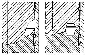
Drop shaped combustion chambers on tubular diesel hammers as shown on the left hand side in Figure 4.11 were made in the USSR at the beginning and now outside as well, but it does not satisfy the driving parameters. During impact fuel is lifted at high speed around the anvil and pressed by centrifugal force to its surface. This reduces uniform fuel allocation in the combustion chamber. Except for the fact that such a combustion chamber does not promote for intensive air circulation during compression, it decreases thermal efficiency during expansion.
Today tubular diesel hammers made in the USSR used a toroidal shaped combustion chamber which makes possible fuel lifting around the sphere after its ejection from the fuel pump, influenced by the diameter d. This is shown on the right hand side of Figure 4.11. This makes for intensive air circulation. In diesel hammers with similar combustion chambers air movement can be observed to be a mixture of three motions:
- radial (down from piston bottom) as a result of being pushed by the piston bottom during downward motion and compression;
- axial (out from cylinder centre axis) by both upward and downward motion of the piston.
- rotational motion in the combustion chamber as a result of air flow from under the piston to the combustion chamber.
Kinetic energy during air circulation seems to be an energy source for mix formation and is given by the expression

where


This expression shows that the smaller 


where
= diameter of piston-anvil spot contact, m
= cylinder diameter, m
Using this expression gives us the possibility of choosing basic parameters for combustion chamber size while aiming to get maximum energy for mix formation (see Table 4.16)
| Mass of Striking Parts, kg | 1250 | 1800 | 2500 | 3500 | 5000 | 7500 |
| Cylinder Diameter, mm | 300 | 345 | 400 | 470 | 550 | 660 |
| Spot Contact Diameter, mm | 102 | 120 | 155 | 170 | 200 | 270 |
| External Toroid Diameter, mm | 240 | 255 | 325 | 370 | 450 | 540 |
| Toroid Radius, mm | 35 | 35 | 46 | 56 | 60 | 61 |
Using these results we can also define the basic parameters of the tubular diesel hammer as follows.
Knowing the mass msv and space Fsv of the pile’s cross section and using a maximum striking velocity of 6 m/sec, the maximum stroke 

where g = acceleration due to gravity, m/sec2.
The mass of the piston-ram in is given from the expression

where
= piston-ram mass, kg
= pile mass, kg
(Editor’s note: this is based on the Russians’ use at the time of dynamic formulae and Newtonian rigid body impact mechanics. For the use of the wave equation, which is current practice, click here.)
One cycle time of the hammer is given by the expression

where t = total cycle time for the hammer, sec.
Of course the blows per minute 

The mean effective pressure (in MPa) is given by

where
= mean effective pressure, MPa
= excess air coefficient = 1.6
= indicated efficiency = 0.40-0.45
= filling coefficient = 0.7-0.8
= specific fuel heat, kJ/kg = 43,260 kJ/kg
= pressure at the beginning of compression, MPa
- for a toroidal type combustion chamber = 0.11-0.12 MPa
- for a swirl type combustion chamber = 0.104-0.11 MPa
= ambient air temperature, °K = 293°K
= theoretical amount of air required to burn 1 kg of fuel, moles
This last quantity is given by the equation

where
= mass ratio of carbon content in 1 kg of fuel = 0.86 kg/kg fuel
= mass ratio of hydrogen content in 1 kg of fuel = 0.13 kg/kg fuel
= mass ratio of oxygen content in 1 kg of fuel = 0.01 kg/kg fuel
The mean effective pressure (in MPa) is also given by

where 
The striking energy of the piston-ram is

where 
and the working volume of the diesel hammer is

where 
The cylinder diameter can then be computed by the equation
![D_{ts} = \sqrt[3]{\frac{4V_h}{\pi k}}](https://s0.wp.com/latex.php?latex=D_%7Bts%7D+%3D++%5Csqrt%5B3%5D%7B%5Cfrac%7B4V_h%7D%7B%5Cpi+k%7D%7D&bg=ffffff&fg=333333&s=0&c=20201002)
where
= 0.95-0.65 (for light diesel hammers k is higher and for heavier ones it is lower)
- s = piston’s working distance from time when exhaust port(s) are covered to impact, m
The combustion unit volume is computed by the equation

where
= combustion chamber volume, m³
= compression ratio = 15
To test the starting quality of the tubular diesel hammer the coefficient of soil resistance is used as follows:

where
= starting quality = 2.5-3
= pile cross-sectional area, m²
, m²
Decreasing “c” lowers the starting quality while increasing “c” increases the length of the hammer.
The parameters for the fuel pump are controlled by the piling. Using the fuel-air relationships we have, the following

as we have seen before.
Parameter Selection for High Speed Diesel Hammers
Blows per minute from a diesel hammer increases by decreasing the stroke while maintaining the impact speed of 6 m/sec. For this reason, the high speed diesel hammer construction has a pneumatic buffer. The basic parameters of these high speed hammers, such as impact speed, striking energy and cycle time are given by the methods of G. I. Cherviakov and Yu. V. Beliaev, as parameters of lifting are calculated with respect to the above given method.
In a diesel hammer with a free falling piston the following parameters are known:
- Vc = combustion chamber volume
- F = area of piston
- s = piston’s working distance
- Gd,ch = mass of piston
- pz = maximum pressure in combustion chamber
- n1 = air compression constant
- n2 = exhaust gas constant
- p0 = atmospheric pressure
- smax = maximum possible stroke of piston
= combustion length of piston movement
= buffer chamber length
= buffer chamber volume
= buffer chamber area
Assuming the buffer chamber area and length, the buffer area is given as the difference between the area of the piston in the buffer and the area of the piston in the combustion chamber. Movement of the buffer is set from the hammer construction solution with respect to its maximum possible height.
The maximum air pressure in the buffer is

where 
The striking energy is given by the equation

where

The impact speed is

and the cycle time is

where

and

Blows per minute can be computed from impact time as before.


6 thoughts on “Diesel Hammers”