
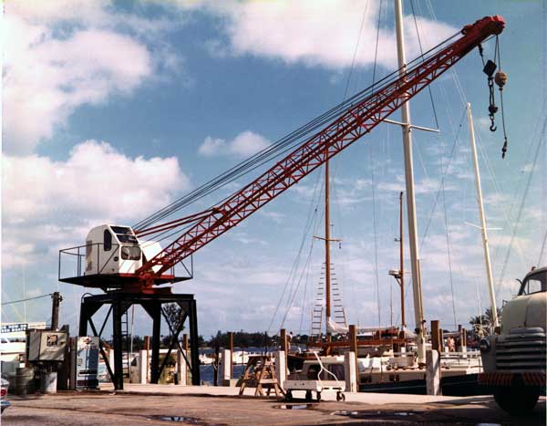
Vulcan produced many products for the coastal and marine industry. When it started producing pile hammers in Chicago, the Loop was moving to other types of foundations. Vulcan–and the Warrington family–was focused on the waterfront, which literally took it all over the world. An example of that is something closer to home: the yard yacht crane shown below, which Vulcan’s West Palm Beach facility produced.
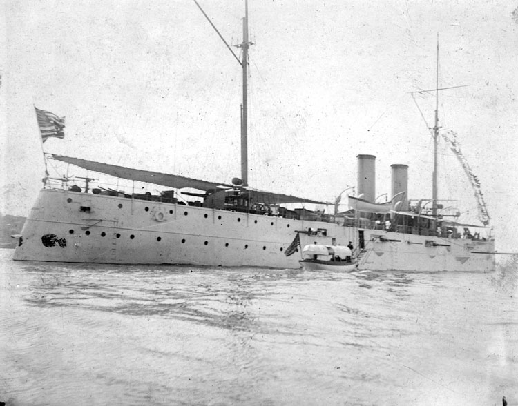
Another device to “haul up” the boat was the davit, shown at the top of the post. These were generally on the ship itself, as you can see below from the U.S.S. Cincinnati, taken June 1896. The davits can be seen with a “lighter” (small boat) in the air, and another one ready to discharge passengers to come aboard, after which it would likely be hauled up.
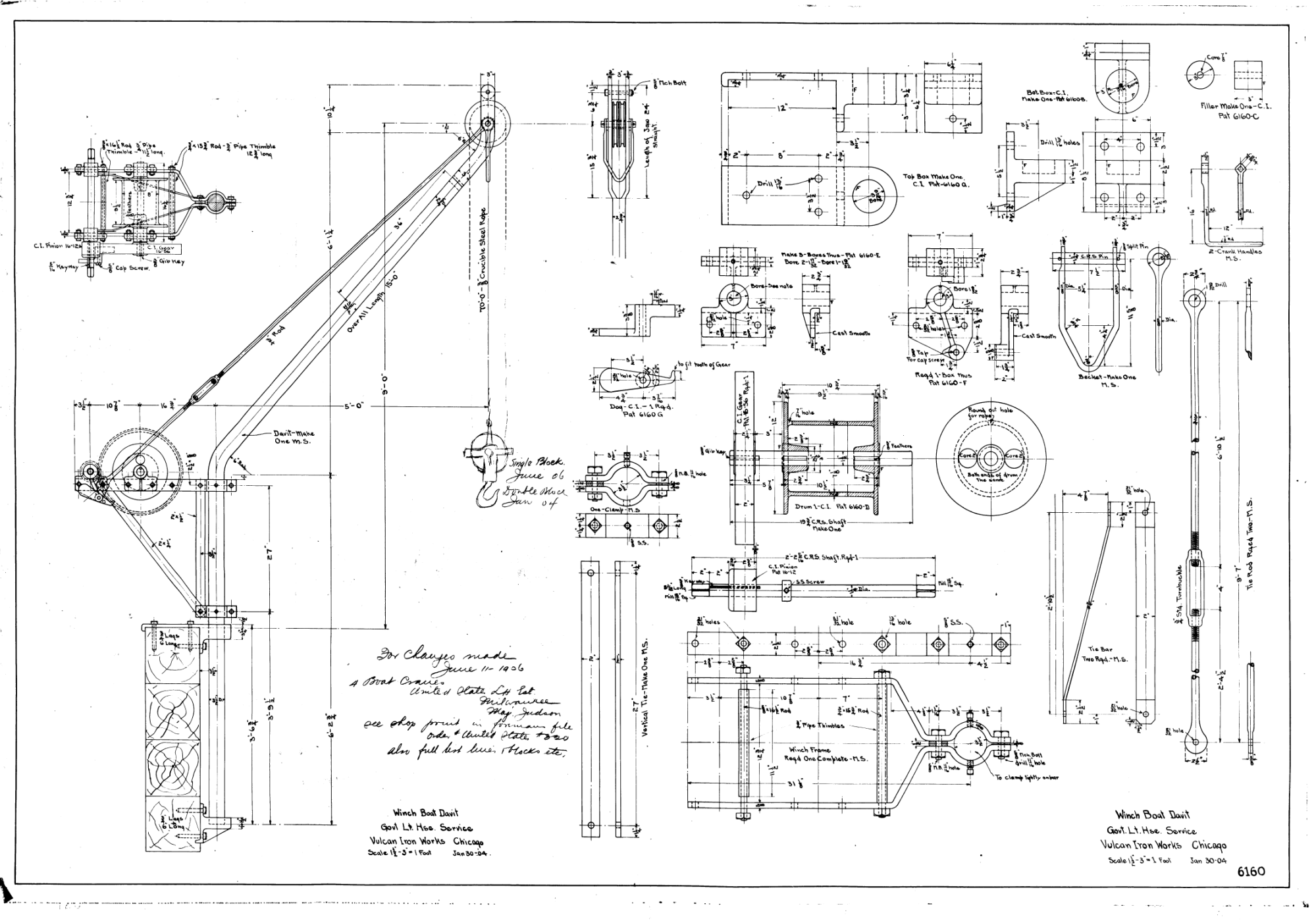
The davit at the top of the post–and the one we’ll be focusing on–dates from 30 January 1904, produced for the “Government Light House Service” (where George Warrington was serving by then, his brothers were at Vulcan) most likely in this case for shore use.
As you can see from the drawing at the top, the davit was basically a bent round shaft which was secured to the boat/land by two revolving supports at the bottom. A ratcheted winch hauled the load up and lowered it. Davits are used in pairs, one at each end of the lighter, and once the boat was out of the water and up in the air, the davits could be swung and used to lower the lighter to the deck or on the short.
The Statics and Design of the Davit
The basic statics of davit design aren’t too complicated, and to simplify things we will do the following:
- We will neglect the weight of the davit’s components, which are probably significant for certain aspects of the design.
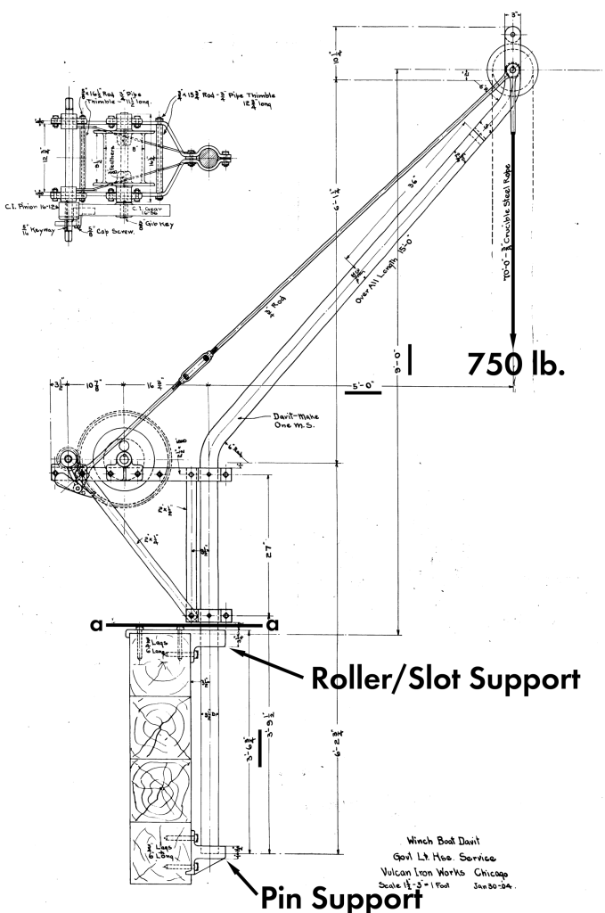
- We will assume the davit is simply supported, as will be evident below.
- We will assume the weight on the tip of the davit is 750 lb. Even though (as the drawing above shows) we could use a two- or four-rope block, that only affects the load the person who cranks the winch, and this is discussed in the post Vulcan 560 Hammer: Specifications and Information.
That said, the static model is shown below:
At this point, we want to do two things:
- Determine the reactions at the supports; and
- Determine the moment at Section a-a
To make things clearer, we will use the CFRAME program to draw the necessary diagrams and to check the analysis. The basic FEA model is shown below.
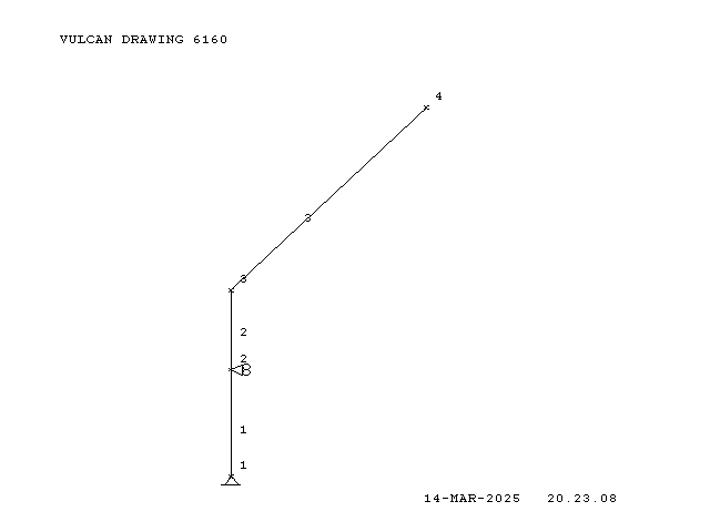
The supports can be clearly seen. The loading diagram is as follows:
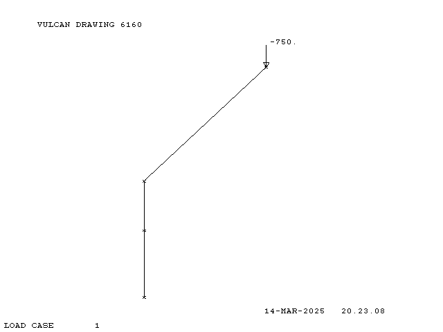
The x- and y-direction load summations and the moment summation around Point 1 (the lower support) are as follows:
Fxu + Fxl = 0 (1a)
Fyl − W = 0 (1b)
−60 W − 42.75 Fxu = 0 (1c)
The coefficients in Equation (1c) are the perpendicular distances from the line of action of the forces to Point 1; these can be seen in the diagram above.
Resolving these is pretty straightforward. In the order of simplest resolution:
Fyl = 750 lb. (2a, the entire weight of the structure is on the lower support)
Fxu = 1052.6 lb. (2b)
Fxl = -1052.6 lb. (2c)
The shear diagram that results is shown below.
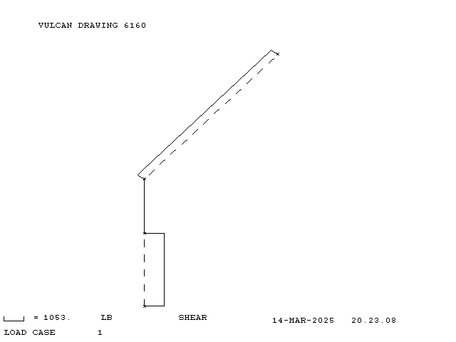
This shows that the reactions arrived at by CFRAME are nearly those of the “hand” solution. Now we turn to the moment diagram:
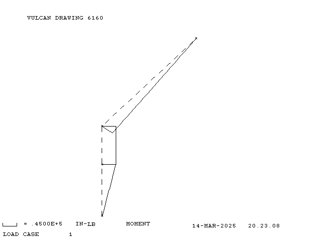
The moment at Section a-a (just above the upper support) can be computed (as was the case in Equation (1c) and is (60)(750) = 45000 in-lb, which is the same as CFRAME.
The deflection diagram (which is beyond basic statics) is now presented.
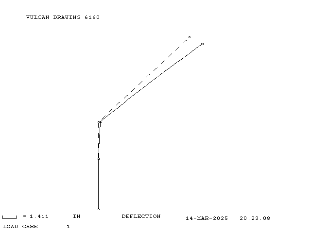
That level of deflection is nothing to sneeze at; however, it illustrates the presence of the turnbuckle-tightened rod, which would stiffen the davit considerably and stabilise the manual raising and lowering of the load. The actual deflection would doubtless be considerably less. None of this, however, affects the maximum moment at Section a-a; that part of the davit is expected to resist the moment from the block and the weight of what’s above it, there is no additional structure that connects the winch and boom portion of the davit with the supports.
If larger loads are desired, the support loads and moments can be raised upwards in a linear fashion.

