
For the rest of the book, click here. For more information on the impact-vibration hammers, click here.
When carrying out excavation work in winter or in permafrost conditions, the most labor-intensive and expensive operation is the loosening (preliminary destruction) of frozen soil. This operation is performed using various mechanisms and devices. All of them have low performance and require a great deal of electrical energy. The use of artificial thawing greatly facilitates soil development, but requires additional time and a large expenditure of funds.
An urgent task is to find new, more effective and economical ways to loosen frozen soil. One of these methods is based on the use of vibratory pile drivers. Back in 1951-1952, during the construction of the pit lintel of the Stalingrad Hydroelectric Power Station, it was found that steel sheet piles, installed under vibratory driving in 1 min., easily penetrated a meter-long layer of frozen sandy water-saturated soil. This observation suggested that vibratory hammers equipped with special devices can successfully destroy frozen soils.
This idea was first implemented by the Lengazstroystroy trust, which, in collaboration with VNIIGS, used a VPM-1 vibratory hammer to punch vertical holes in frozen soil (for the purpose of installing electric heating needles) [39]. Here, under the technical supervision of I.F. Kostikov and M.I. Mayrygin, a special sliding installation was constructed (Fig. 123), which consists of a U-shaped metal welded frame on wheels. A vibratory hammer moves along the frame posts using a roller device. It is raised and lowered using a manual winch; you can also move the installation along the work area manually.
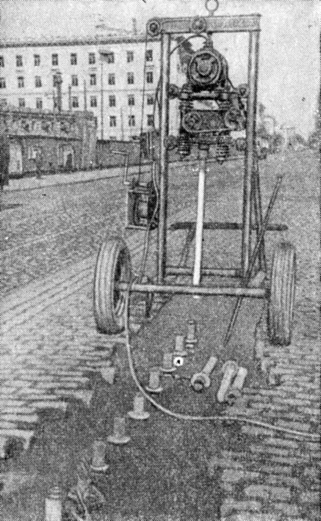
To punch holes in frozen soil, a special punch was used, rigidly attached to an impact-vibration hammer, which was a massive steel blank with a diameter of 57 mm and a length of 1.2 m with a pointed tip. The installation was serviced by two workers. After the installation was put into place, one of them turned on the electric motor of the vibratory driver, and the other released the winch safety lock, and the punch was immersed in the ground to a depth of 1 m. The punch was removed with the vibratory driver running and an electric device was inserted into the hole. Subsequently, the installation was moved to the next stop, and the electric needle was connected to the network.
The work was carried out in various areas of Leningrad. The thickness of the frozen soil layer was 0.9-1 m. The duration of one full cycle of work was on average 11.7 minutes, and the immersion of the blank was from 1.25 to 2 minutes. Installation capacity is 40-45 wells per shift.
It is interesting to note that, simultaneously with a vibratory hammer, a S-57 drilling machine with electric drills with a diameter of 57-60 mm was used to construct the same wells. Its productivity did not exceed 25 wells per shift, i.e. it was 40% lower than the productivity of an installation equipped with a vibratory hammer, which also turned out to be more economical in all respects.
To test the possibility of destroying frozen soil using an impact-vibration hammer, special experiments were carried out. A steel blank of the same dimensions as for drilling holes, but in the shape of a chisel, was attached to the impact-vibration hammer. Submerged by a vibrator, it also demolished the soil, like a jackhammer. The separation of blocks of frozen soil measuring up to 0.4 m in diameter occurred when the blank was immersed to a depth of 0.2-0.4 m, and the immersion lasted no more than 5 seconds.
Experiments have convincingly shown that using vibratory hammers can create effective installations for the destruction of frozen soils. Depending on the condition, they can be designed either according to the simplest scheme, providing for the movement of the working body only in one specific direction in relation to the supporting mechanism (trolley, tractor, etc.), or according to more complex schemes, providing the ability to manipulate the working body at each stop in a plane or in space. The first of the schemes will be rational for a wide scope of work, more complex ones – when excavating soil in small pits and narrow trenches.
An example of a device of the first type is an experimental caving machine; its design was developed in 1952 by V.I. Chernyaev and N.A. Marchenko at the suggestion of V.I. Platov. The machine (Fig. 124) consists of two main parts: a vibrating wedge and a guide support stand, which provides the required angle of inclination of the vibrating wedge, as well as lifting it from the face and moving it along the collapse front. The vibrating wedge (Fig. 125) – the working part of the machine, is a rigid steel frame, covered with a shell of sheet steel. Inside the frame there is an impact-vibration hammer TsNIS-1 of the S. A. Tsaplin system and a guide jaw hinged to the frame.


The power of both electric motors of the TsNIS-1 vibratory hammer is 8.4 kW, the speed is 2950 RPM and the maximum eccentric moment is 100 kg-cm. Without a vibrating wedge, the weight is 1.4 t.
The machine was tested on thawed and frozen soils: it was placed at the top of the face in such a way that the distance from the vibrating wedge to the edge of the slope was 0.4-0.6 m. Depending on the steepness of the face slope, the vibrating wedge was installed on a guide support stand at an angle from 40 to 70° to the horizon, so that the subsequent movement of the wedge during the process of soil collapse occurs along a plane parallel to the surface of the face slope. When the winch brake was released, the vibrating wedge, under the influence of its own weight, fell along the guide stand and rested against the ground with its cutting edge. Then the impact-vibration hammer was put into operation, after which the vibrating wedge crashed into the ground, moved down the slope and collapsed the soil to the base of the slope.
To determine the effectiveness of a vibrating wedge when collapsing frozen soils, experiments were carried out in sandy loam soils, in a face up to 2.5 m high, with a slope angle of 70°. The chipping of soil frozen to a depth of about 1 m was carried out using a wedge without teeth with a sharpening angle of 20°; the vibration amplitude of the wedge was only 2 mm. Despite the obviously unsuccessful vibration parameters – too high a frequency and insufficient amplitude, the results were positive. The vibrating wedge reliably destroyed frozen soil, and the specific energy intensity of the process did not exceed the usual one that occurs with other methods of destroying frozen soil.
Since when chipping frozen soil there is no lateral resistance to the movement of the working part of the machine, it is hardly advisable to use vibratory hammers. A greater effect will be achieved by using vibratory drivers such as the VPP type, provided that the electric motor is moved to a part of the machine isolated from vibrations, vibratory drivers of the simplest type can also be used.
Fig. 126 shows a diagram of the design of a self-propelled installation for destroying frozen soils, equipped with a VPP-type vibratory driver.


One thought on “Application of Vibratory Hammers in the Development of Frozen Soils”