
Editor’s Note: in part as a follow-up to this post, I am putting up a translation of this chapter from the “seminal” classic on the subject of vibratory and impact-vibration pile driving. It is interesting to note that the lead designer on the original models of vibratories with both translational and rotational motion is M.G. Tseitlin, who thirty years later was the lead author of our first serialised Russian book, Vibro-Engineering and the Technology of Piling and Boring Work. He has an entire chapter on the theory behind the subject, albeit from a more numerical approach.
In recent years, construction has been characterized by a move away from massive deep foundations and the widespread introduction of supports on pile grillages of various types. In most cases, these supports are much more rational than, for example, coffered foundations, since they are cheap, faster to install and require less material, the excess weight of which causes significant settlement.
N. M. Gersevanov [19] pointed out that foundations on piles of large diameter are especially advantageous, each of which is able to withstand a load of several hundred, and sometimes thousands of tons. The construction experience of recent years has shown that among such piles, prefabricated reinforced concrete shell piles are the most rational, since their use makes it possible to widely industrialize the work of building foundations. How significant the resulting economic effect can be judged from Table. 18.
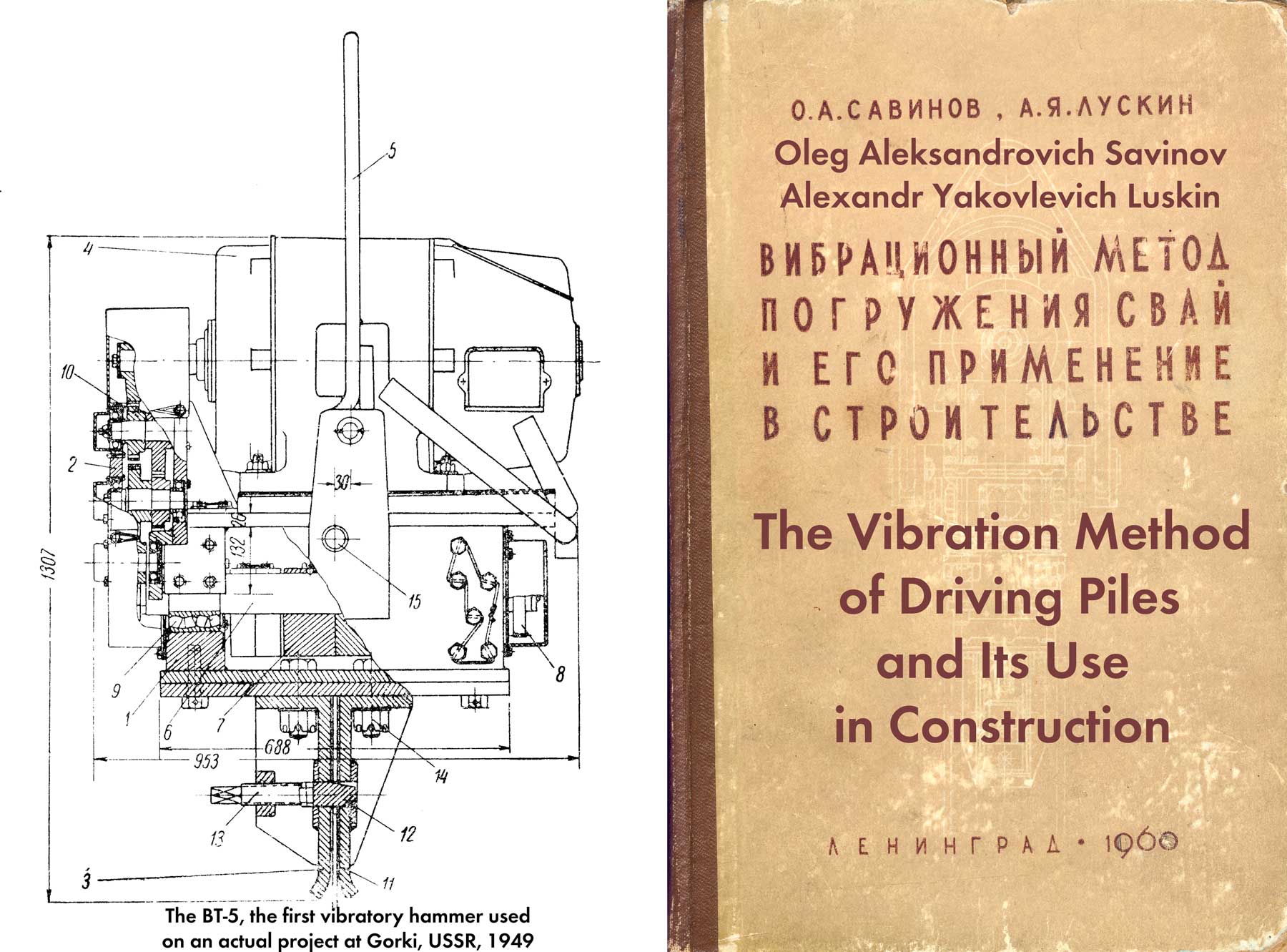
In the postwar years, B. P. Tatarnikov [58], L. I. Vasiliev [15], K.S. Silin [54], V. I. Karpinsky, A. P. Gertsov, A. P. Tamarov [21] and others developed a technology for driving reinforced concrete pile-shells using low-frequency longitudinal vibratory drivers of the types VP-1, VP-3, VP-4, VP-5 and VPU-A, description. of which is given in § 6 of this chapter.
As noted, the experience of using these machines in general gave positive results. On a number of large bridges, with their help, piles with an outer diameter of up to 1.55 m and a weight of up to 50 tons were driven to a depth of up to 23 m . At the same time, it was found that vibratory hammers of this type have a low loading capacity, give low sinking speeds, and also require the installation of high-power engines. Suffice it to recall that each of the VPU-B vibratory hammers, designed for immersion of shells with a diameter of 2-3 m, weighs 12.5 tons and were equipped with electric motors with a total capacity of 310 kW.
| Indicators | Foundation types | ||||
| coffered | Drilled Shafts | grillages on wooden piles | grillage on steel pipe-concrete piles | grillages on reinforced concrete piles-shells of large diameter | |
| Total Foundation Cost in % | 100 | 90 | 60 | 50 | 40 |
| Labor costs in % | 100 | 90 | 40 | 35 | 25 |
In this regard, it became necessary to find ways to increase the efficiency of vibration machines for driving heavy reinforced concrete shell piles in order to reduce the power of the machines and increase their productivity.
One of these methods may be the use, in addition to the longitudinal, of rotational vibrations of the shell pile when it is immersed. For ordinary piles, the transverse dimensions of which are small compared to the length, this method is not feasible, since the application of significant torsional disturbing pairs would result in twisting of the pile up to its complete destruction. Unlike conventional piles, the shells have very significant torsional rigidity and strength. As a result, rotational vibrations of any intensity can be imparted to them.
Since pure rotational vibrations cannot contribute to overcoming the drags of the soil, they will be useful only when the drags are completely eliminated (for example, by excavation), but they are unsuitable in cases where such drags are present. On the other hand, with separate longitudinal or rotational vibrations, the movement of the pile in the process of immersion occurs with two stops in each period. At those moments when these stops occur, the resistance of the soil to the movement of the pile increases sharply, which entails a significant decrease in the average sinking speed and an increase in energy costs to overcome the resistance. If, however, longitudinal and rotational oscillations are used together, then, under certain conditions, it is possible to obtain such an oscillation mode in which the movement of the pile will occur without stopping at all.
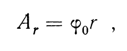
Consider the displacement of some point on the surface of an oscillating pile-shell. With longitudinal vibrations, this point will move in a straight line parallel to the pile axis, and with rotational vibrations, in a circle with a radius r lying in a horizontal plane. Imagine that we have superimposed the first type of oscillation on the second with a phase shift of 90º, i.e., in such a way that
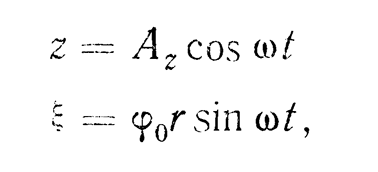
Where
the amplitude of longitudinal vibrations;
angular amplitude of rotational oscillations.
Under the condition (2.9), the locus of the ends of the velocity vector will be an ellipse, the equation of which is:
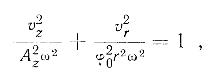
where
the vertical component of the oscillation velocity;
tangential component.
It can be seen from this that in this case, the oscillations of the pile will occur without stopping.
Based on the above considerations, the authors, together with M. G. Tseitlin, in 1952 proposed the use of vibration machines for driving cylindrical shell piles, capable of inducing longitudinal-rotational vibrations that meet the condition (2. 9), and developed an appropriate design of a double vibrator actions. Later, M. G. Tseitlin [61] considered the problem of changing the friction forces during rotational and longitudinal-rotational oscillations, and also conducted a series of experiments aimed at verifying the correspondence to nature of the theoretical conclusions obtained; The main results of this work are presented below.
Let us consider the motion of a certain point K on the surface of a submerged pile-shell, which performs rotational oscillations around its vertical axis. This point is involved in a complex motion, and its velocity 


We have

where 
The angle γ between the direction of the axial and total velocities is characterized by the ratio of the values of these velocities:

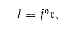
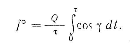
The impulse I of the friction forces acting in the direction of the axis of the shell on its surface over a period of 

where T = the total value of the friction force acting on the shell.
On the other hand, the impulse I can be written as the product of the friction force 

Comparing formulas (2 12) and (2 13) with each other, we obtain the following expression for the average friction force:
Assuming 

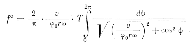
Reducing the resulting integral to an elliptical integral of the first kind, we represent the expression (2.15) in the following form:
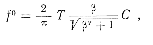
Where

Given different values of β, and using tables for calculating elliptical integrals, it is not difficult to plot the change in the friction force during rotational vibrations of the shell-pile, which performs translational motion along the axis (Figure 53). For comparison, the dotted line shows the curve constructed by Yu. I. Neimark for the case of longitudinal oscillations of the pile.

Proceeding in a similar way, M. G. Tseitlin obtained similar formulas for determining the value of

The average friction force in this case will be expressed by the formula:
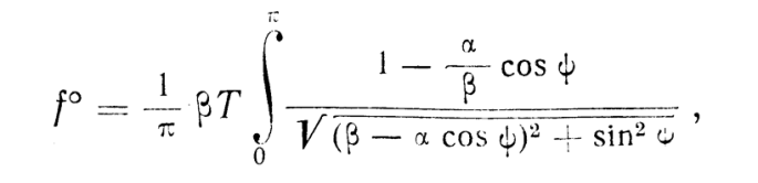
Where

The integral in this formula can no longer be expressed in terms of elementary functions. An approximate calculation of it using the Simpson formula makes it possible to plot graphs (Figure 54) of changes in the average friction force during longitudinal-rotational vibrations depending on the parameter 
On Figure 54a, graphs of dependence 
On Figure 54b shows similar graphs for longitudinal-rotational oscillations with a phase shift of 90º. Both the one and the other graphs show families of curves for different values of α.
It can be seen from the graphs that the most effective decrease in friction forces takes place during longitudinal-rotational vibrations of the shell with a phase shift of 90º, when 

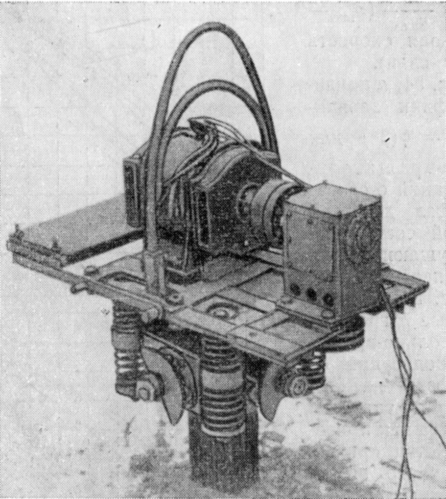
To carry out experimental work on the study of longitudinal-rotational oscillations, M. G. Tseitlin proposed a new scheme and developed the design of an experimental combined-action vibratory driver (Figure 55), which makes it possible to report oscillations of various directions to the submerged shell model.*
* M. G. Tseitlin, Author’s certificate No. 118227 with priority dated April 10, 1953.
Experiments carried out M. G. Tseitlin on immersion of models of pile-shells with a diameter of 120-273 mm, confirmed the correctness of the given benefits. As it turned out, longitudinal-rotational (double) oscillations provide a higher speed and greater depth of immersion than pure longitudinal ones, and at the same time require less energy.
Longitudinal-rotary vibrators that excite a longitudinal disturbing force and a torque that differs in phase by 90° (for brevity, we will call them double-acting vibratory drivers) can be built according to various schemes. The simplest schemes are shown in Figure 56.*
*The figure shows the diagrams of the device of the double-acting vibratory hammers of the simplest type. However, at a high vibration frequency, vibratory hammers of this type with sprung surcharge can be built. as, in particular, it was carried out by M. G. Tseitlin in a vibratory driver of the VKD type.
The device of a double-acting vibratory driver (Figure 56a) differs from the device of longitudinal-acting vibratory drivers in that its eccentrics 1 rotate not in one, but in two different planes located symmetrically relative to the longitudinal axis of the machine at a distance R from it. As in a conventional directional vibrator, the synchronization of the rotation of the eccentrics is ensured by the presence of two gear wheels 2. The drive 3 is no different from the usual one (see Figure 27).
The vibratory driver, built according to the second scheme (Figure 56b), is distinguished by the fact that the eccentrics 1 are fixed on coaxial shafts, the synchronization of rotation of which in different directions is provided by three bevel gears 2. The second distinctive feature is the use of a vertical motor 3 in the drive.
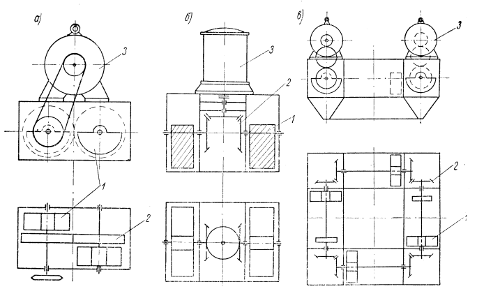
The first two schemes are quite suitable for low-power double-acting vibrators. For more powerful vibratory loaders, a four-shaft scheme can be used (Figure 56c), which allows you to place four eccentrics 1 at a sufficient distance R from the longitudinal axis of the machine and create eight bearing supports that carry disturbing forces. This scheme makes it possible to manufacture vibratory drivers with a hole in the body, which allows, simultaneously with the immersion of the shell pile, to excavate soil from its cavity with special grabs, similar to what is done in longitudinal vibratory drivers of the NVP-56 and VP-6 types.
Synchronization of rotation of the shafts with eccentrics is provided by four pairs of bevel gears 2, and the drive is carried out using two electric motors 8, located symmetrically about the longitudinal axis.
The above schemes are far from exhausting all possible options for the design of double-acting vibratory hammers. Of considerable interest are also such schemes that allow the creation of universal vibratory drivers capable of operating in different vibration modes.
Several such schemes can also be proposed. One of them is the simplest and is the basis for the design of a powerful experimental vibratory driver developed under the guidance of the authors and called VDD-2.* This scheme allows you to create a design of a vibratory driver, which, by simple permutations of eccentrics, can be tuned to any of the following vibration modes: pure rotational, longitudinal-rotational with a phase match between the longitudinal force and a twisting pair (screw), longitudinal-rotational with a shift of the indicated phase by 900 (double) and clean longitudinal. It is also possible to adjust the vibratory driver for double vibrations of several types, which differ in the value 
*S.V. Plekhanova and Yu. G. Melart took part in the development of the design.
The main purpose of the VDD-2 type vibratory driver is to immerse shell piles in various soils: from weak water-saturated and dry sandy-gravelly to dense clays. Depending on the properties and density of soils, shells can be immersed without excavation of soil from its cavity or with simultaneous removal of soil by an airlift, hydraulic elevator or a special grab without removing the vibratory driver from the shell.
The field of application of the vibratory driver and its parameters were determined taking into account the fact that hollow piles and thin-walled shells with a diameter of 0.8-1.6 m are most widely used in construction at present. Therefore, the purpose of the first sample of the new machine was limited to 1.5-2 m.
Vibratory hammer type VDD-2 (Figure 57) has the following technical characteristics:
| static moment of eccentrics, adjustable in steps | 10 000-40 000 kg-cm |
| oscillation frequency continuously adjustable | 200-500 per min. |
| the largest value of the amplitude of the longitudinal disturbing force | 112 t |
| the largest value of the amplitude of the moment of the rotating pair of disturbing forces | 112 tm |
| power of two electric motors | 200 kW |
| total weight of the vibrator. | 13 m |
| overall dimensions n plan | 3200 x 2680 mm |
| full height | 2000 mm |

The vibrator consists of a vibrator 1, electric motors 2 with a drive, a special adapter (head) 3 and a cable suspension 4. The device of the machine (Figure 58) is very simple. In the welded housing 1 on eight shafts 2 eccentrics 3 are placed, which are a half circle with a hole in the center formed by a removable clamp. eccentrics can be fixed on the shafts with two keys in different positions. Shafts whose axes intersect at one point lying on the longitudinal axis of the machine are supported by sixteen tapered angular contact roller bearings 4.
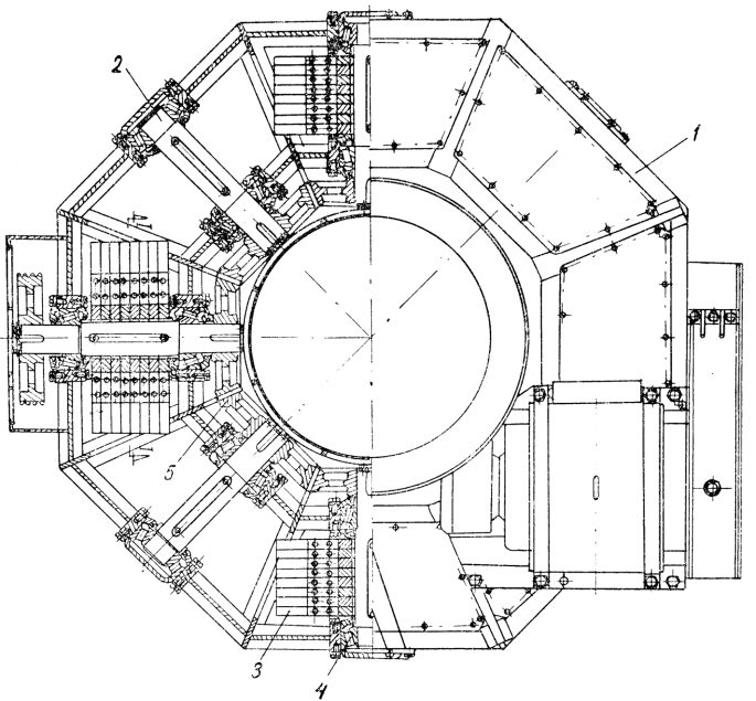
Synchronization of the rotation of the shafts with eccentrics is carried out by eight bevel gears 5, which are meshed with each other.
The drive of the vibrator consists of two electric motors of the AK type with a phase rotor and two chain drives connecting the electric motors to the drive shafts of the vibrator.
The vibrator is fastened to the shell pile to be driven using an adapter having a flange with holes at the bottom, which is bolted to the same flange on each shell pile. The number of bolts and the dimensions of their cross section are taken in such a way that they easily withstand the longitudinal forces and the torque of the disturbing forces.
If all 32 eccentrics are placed only on four shafts (through one) as shown in Figure 58, then the mode of double oscillations will take place in the vibratory driver of the VDD-2 type. What will be the dependence of the magnitude of the amplitude of the longitudinal component and the magnitude of the linear amplitude of the rotational component with such an arrangement of eccentrics? As already mentioned, the amplitude A of the longitudinal oscillations of the shell can be determined from the approximate dependence (2.1). The linear value of the amplitude of the rotational component of oscillations, as is known, is equal to
where
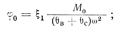
the radius of the outer surface of the pile-shell;
the amplitude of the torque of the disturbing forces;
respectively, the moment of inertia of the mass of the vibrator and the pile relative to its longitudinal axis;
angular frequency of oscillations.
If we assume that the entire mass of the vibratory driver is concentrated along the circle passing through the centers of gravity of the eccentrics, and the mass of the shell pile is concentrated along the circle passing through the middle of the wall thickness, then
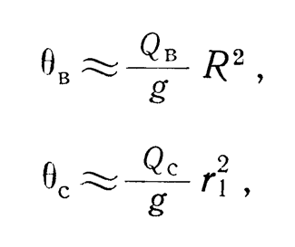
where 
Substituting the values (2.21) and (2.20) into (2.18), taking into account that

and assuming approximately both of the top expressions
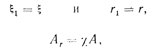
Where
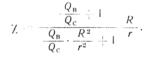
From expression (2.22) it can be seen that the linear value of the amplitude of rotational oscillations differs from the amplitude of longitudinal oscillations by the presence of a coefficient 

 on the ratio for various values of the ratio of the weight of the double-acting vibratory hammer to the weight of the immersed shell:
Graphs of the dependence of the value of the coefficient 
In a VDD-2 type vibrator, in which R = 1 m is adopted at r = 0.75 – 1.25 m, the 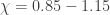
Recently, it has become necessary to immerse thin-walled prefabricated reinforced concrete cylinders with a diameter of 4-6 m into the ground, intended as foundations for bridge supports, water intake devices, the main structures of embankments and other structures.
In this regard, the authors, together with M. G. Tseitlin, proposed a new device and developed the design of a double-acting vibratory installation of the VDD-3 type, with which it is possible to immerse reinforced concrete cylindrical shells with a diameter of 1.5 to 6 m and a length of up to 50 m.
This universal machine can impart to the submerged shell rotational, longitudinal and longitudinal-rotational vibrations with different ratios between the amplitudes of the longitudinal and rotational components of the vibrations.
Unlike other machines of this type, the VDD-3 vibration unit consists of separate single-shaft vibrators of non-directional action, interconnected by a mechanical synchronization system.
Figure 60 shows a general view of the VDD-3 vibration unit mounted on a shell with a diameter of 4 m. Figure 61 shows the non-directional vibrator included in the machine. As can be seen from the figures, the vibrator is driven by an electric motor, which transmits the movement to the unbalanced shaft. At the end of the shaft, a bevel gear is mounted, which engages with the same gear of the synchronizer shaft. The synchronizer bevel gear can engage with the same gear on the vibrator shaft from different sides, relative to the vertical plane passing through the longitudinal axis of the vibrator shaft. This is achieved by rotating the bevel gear housing 180º relative to the vibrator housing and locking it in the new position.
The ability to change the location of the synchronizer bevel gears allows you to set the direction of rotation of the eccentrics without changing the direction of rotation of the synchronizer shafts, which ensures that the installation is configured for double, longitudinal and rotational vibrations.

The vibrators are mounted on a replaceable support ring and connected by universal shafts. The replaceable support frame can be made lighter than the massive adapter foundation of existing longitudinal vibrators, where this adapter must transfer the disturbing force acting near the central vertical axis of the shell to its walls.
The vibrators included in the VDD-3 vibration unit have the following technical characteristics:
| disturbing force | 50 t |
| moment of eccentrics | 10 000 kg-cm |
| oscillation frequency | 300-670 per min |
| motor power | 55 kw |
| weight | 3 t |
Depending on the size of the shells to be submerged, the vibratory unit may include a different number of vibrators – from two to ten. Twin vibrators can also be used as longitudinal vibrators for driving heavy reinforced concrete piles.


One thought on “Rotary Vibratory Hammers”