
In some manufacturers’ literature, you’ll see the “section modulus” of leaders as part of the specifications. (Ironically, Vulcan never put this in their specifications.) So what is this? How is it derived? And how is it useful? Are there any things we need to understand in using it? (The answer to the last is “of course,” like anything else in engineering.) This article shows how it’s derived and how to apply it, along with its limitations.
The Basics
Conventional beam theory tells us that the stresses in a beam due to a moment can be computed by the equation

where
tension or compressive stress in the beam
moment at a given point in the beam
distance from neutral axis to extreme fiber (upper or lower edge) or beam
moment of inertia of beam
If we define the section modulus

then

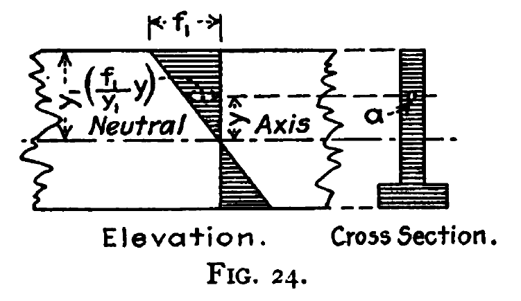
This can be illustrated for two cross sections below, from Thomson (1910)

Many mast-type leaders use continuous beams of one kind or another, and they can be analyzed directly using the equations above. Conventional, U-type leaders are more complicated and their analysis is below.
Figure 23 suggests that the compressive stresses above the neutral axis could be concentrated into a force and the tensile forces could be compressed into another. That’s crucial in our understanding of how leaders work.
One more basic fact is the parallel axis theorem. The moment of inertias you see for beams, pipe, square tubing, etc. are traditionally computed at the centroid (centre of gravity) of the section. To compute that at another point 1 

where A is the cross-sectional area of the beam, etc.
Developing the Equations
Let us consider the following leader section.


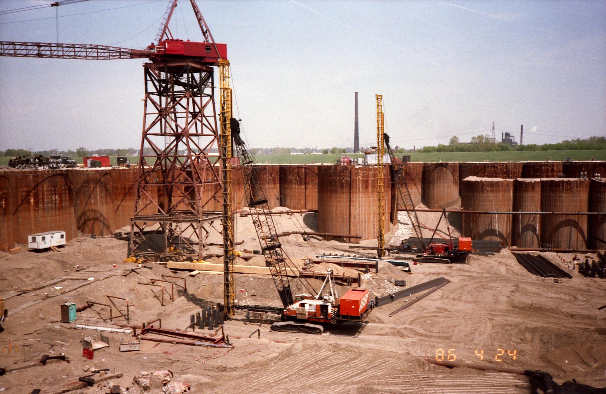
Use of square tubular leaders, today almost universal with onshore leaders, was not always the case. Vulcan used the “beam and channel” configuration for many years, adopting tubular leaders in the early 1970’s, as can be seen at the right.
In any case we have two sets of “legs” for the leaders: the front legs, where the hammer runs in the leaders, and the back legs, where the yokes and struts are welded to, holding the leader section together.
Unless the front and back legs are identical (which isn’t often the case) the centroid of this “beam” is not halfway between the two legs. Using the back legs as our “zero” coordinate, the distance of the centroid from the back legs is

where 
If both sets of legs were at the centroid, then the moment of inertia would simply be the sum of the moments of inertia of the legs. That wouldn’t be very useful; it is necessary to “move” the front and back legs to their respective position. Doing that yields the moment of inertia for the entire leader section, thus,

At this point we can apply Equation (2) to determine the section modulus. The problem is that we usually have an asymmetric cross-section (see Figure 24) and so there are two values of c, thus


The two section moduli that result are


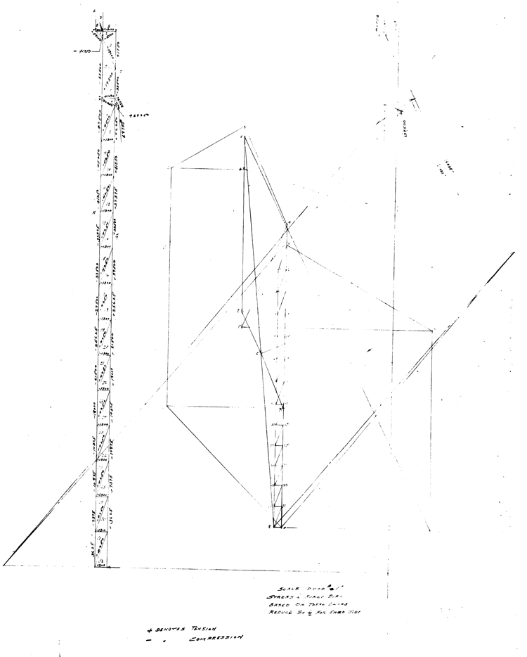
One thing worth noting is that, for most leaders, the second term (the “parallel axis” part) of Equation (4) tends to dominate the computation of the leader section modulus over the first term (the “beam” part.) In its earlier years, before more advanced computation arrived, Vulcan analysed its leaders and other structures as trusses, ignoring the bending resistance of the members, and did so successfully. In that scenario the legs are in compression on one side and tension on the other, depending upon the orientation of the leaders, and this is certainly a valid way to look at how leaders are loaded. It also puts a premium on the integrity of the section connections, an often overlooked aspect of leader design.
Application
There are two critical moments in the use of leaders: when you first pick them off of the ground, and when you’re in a batter driving pile. We will start by considering the second loading case first.
How the leads are loaded in both cases depends upon many things, and varies on a case-by-case basis. A typical loading scheme has two components: the self weight of the leads per foot 


Using Equation (3), the maximum extreme fibre stress in the leaders is the larger of

or

If we substitute the values shown in Figure (1), the first thing we determine are the moment of inertia and the section moduli. Using Equations (6) and (7),


We substitute these and the other values into Equations (10a) and (10b) for the following result.

It is evident that the maximum stress is governed by the back legs, which is not unusual for leaders. It is also evident that, as the batter increases, the stress increases at an accelerating rate, which is one reason why is more difficult to design successful leader systems for high pile batter.
Turning now to picking up the leaders from the horizontal, the first thing you do is to push the hammer to the bottom of the leaders. Failure to do this is an unsafe condition; not only do you overload the leaders, but once the leaders are being raised the hammer can come screaming down the leads, endangering personnel and equipment at the bottom.
Once you’ve done that, again the leaders can be modelled as a simply supported beam, the maximum moment can be computed by the equation
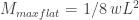
and the stresses can be computed using Equation (3). Doing that yields the front and back maximum fibre stresses of 4763 and 9577 psi respectively.
Limitations and Lessons
- The section modulus method, while useful in analysing a set of leaders for a particular application, has several limitations:
- The leaders aren’t a real “beam” in that there is no continuous connection between the front and back legs, but a system of yokes and struts. That results in secondary stresses, which raise the stress levels in the leaders beyond what is computed here. An allowance needs to be made for this in actually evaluating leaders.
- The section modulus method ignores many important aspects of leader design, such as the effect of side batters, the integrity of the connections, the design of the leader connections with other parts of the system (such as crane boom points) and other parts of the system.
- As leaders age, they will corrode, and their section modulus will decrease. It is important to do periodic inspection of leaders, not only to check the integrity of the welds, but also for the general integrity of the members. Local damage of the leaders will also degrade their performance, and this too should be noted in inspections and properly repaired.
One way to get around this problem in the initial design is to use finite element analysis, and an example of this from Vulcan is shown below.

- Inspection of Equations (9) and (11) will show that limiting the unsupported length of the leaders is crucial in controlling stresses during use. This is an advantage of fixed and underhung leaders and a disadvantage of using swinging leaders on a batter. Unless some intermediate support is used with swinging leaders–which can make for complicated crane handling–the section modulus requirements for leaders with long unsupported lengths can be difficult. Examples of both are shown below.


Conclusion
The section modulus method is a useful tool for analysing leaders for a specific application. It must be used with care, understanding its limitations and taking into consideration all aspect of leader design and use.
References
Thomson, W.C. (1910) Bridge and Structural Design. New York: Engineering News Publishing Company.


2 thoughts on “Section Modulus of Pile Hammer Leaders”