

As indicated above, the questions of nonuniformity in the rotation of eccentrics and the limited drive power are as a rule considered in studying dynamic loads in the drive of the vibrodriver and vibrating hammer, and also in determining the power required.
Nonuniformity in the rotation of the eccentrics is caused by:
- variation in the moment of gravitational force of the eccentric relative to its axis of rotation;
- variable acceleration of the axis of rotation of the eccentric;
- inconstancy in the moment of the drive engine and its limited power;
- variation in the rotational resistance of the eccentric.
I. I. Bykhovskii investigated the variations in the angular speed of rotation of the eccentrics as a result of impacts with an immoveable limiter and a limited driving power. M. A. Gurin studied the influence of the limited power on the working regime parameters of an impact-vibrational earth-preparing machine and the moment developed by the drive, and also optimized the parameters of the vibrating hammer in order to obtain the maximum impact speed.
The dependences of the sinking depth of the element for one impact on the basic parameters of the vibrating hammer and the characteristics of the drive engine are revealed in the present section and the power consumption in driving piles are also determined (G. G. Azbel and B. B. Rubin, 1980).
The stable periodic movement of a system with a period T = 2π/αav, where αav is the mean value of the angular velocity of rotation of the eccentrics for a period, is examined. Just as in Section 7, it is assumed that the element to be driven is immobile during the flight of the hammer and the soil resistance during the movement of the pile has a purely plastic nature.

The calculation model of the system is shown in Figure 36.
The limiter of the impact part is modelled by a high-rigidity spring, which is selected from the conditions of correspondence with the experimental data on the duration of the impact (A. S. Golovachev and V. P. Ivanov, 1968).
The working section of the static characteristic of the engine can be described by the equation (V. S. Shevchenko, 1960)

where a and b are constant coefficients, dependent only on the characteristics of the engine.
For the calculation scheme shown in Figure 36, the first movement stage, flight of the impact part, is described by the equations:


at 
The conditions of the beginning of the raising of the impact portion at t = 0 are determined by the relation:

The flight of the vibrating hammer ends at the moment t = t1, of contact of the impacter and limiter. Compression of the limiter takes place in the second stage up to the beginning of movement of the element to be driven:
 (58)
(58)
In the system of equations (58) c2 » c1 and therefore c1 can be disregarded in performing the calculations. The boundary conditions at t = t1 for Eqs. (56) and (58) have the form:
![]() (59)
(59)
In the third stage (t2 ≤ t ≤ t3) the speeds of the vibrating hammer and pile are equalized:
 (60)
(60)
At the boundary t = t2 of the second and third stages:
 (61)
(61)
The fourth stage (t3 ≤ t ≤ t4) is characterized by the joint movement of the vibrating hammer and pile with a compressed limiter:
 (62)
(62)
At the boundary t = t, we have:
.![]()
The movement is completed at the time t = t4 , stoppage of the system, where

During the stoppage of the system there is only rotation of the eccentrics, described by the equation
![]() (63)
(63)
The final conditions for Equation 63 are:
![]() (64)
(64)
The mathematical model of the calculation scheme of Figure 36 should be solved by using the method of successive approximations because at the beginning of the calculation the values of αo and 


Therefore, it is logical to set the value 
It follows from the above that solution of the problem should begin with calculation of the value αo according to the set 

After finding αo, and
and the mean value of the angular velocity of rotation of the eccentrics per cycle

In this case the mean power of the engine 
In solving the differential equations of the corresponding movement phases on a computer, the following dimensionless variables and parameters are introduced:
 (65)
(65)
It is established with the calculations performed that the displacement Y of the pile for one impact and the power N required by the vibrating hammer are nonlinearly dependent on the parameter ξ2, which characterizes the rigidity of the limiter; when ξ2 > 50, the driving ability and power of the vibrating hammer are practically independent of the value ξ2. This result is obtained for various degrees of soil resistance.
Figure 37a plots the dependencies of the driving ability of the vibrating hammer on the parameter h at 

The variation in the ratio of power required by the electric motor of the vibrating hammer to the sinking depth per cycle is plotted in Figure 37b. This value, which is one of the criteria for efficient operation of the vibrating hammer, has minimal significance at h = 0.4. The non-uniformity of the angular velocity per cycle 
One of the components of the value h is the parameter d, which is the ratio of the amplitude value of the compelling force (with 

The parameter λo has an insignificant influence on the basic technological characteristics of the process: the sinking depth, the power required, etc., but it does determine the dynamic stability of the process.
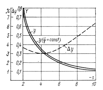
The dependence of the sinking ability of the vibrating hammer on the dimensionless rigidity of the springs ξ1 is analogous to the dependences obtained without taking the non-uniformity of rotation of the eccentrics into account. The relative deviations in the results of calculating Δy in both models are a function of the parameter 1/d. When 1/d ≈ h, these deviations are not great and range from -1 to +5% for various ξ1 values when s = —8. These deviations increase with decreasing resistance of the soil and attain 10% when s = —4 and ξ1 = 0.6.
In selecting the optimal values of the parameters d, ξ1, and λo, the nature of the dependence of the sinking ability of the impact-vibration machine on the dimensionless resistance of the soil is in accordance with the results obtained in examining the dynamics of the process of impact-vibrational sinking, disregarding the non-uniformity of rotation of the eccentrics and the rigidity of the limiter (Figure 38). The deviations in the calculation results obtained for the various models have an essentially nonlinear nature and a maximum at s = -4.
The investigations reveal that with the calculation scheme assumed and the assumptions on it, in spite of some increase in the impact velocities of the vibrating hammer with an increase in the resistance of the soil, the useful work of the. vibrating hammer (

All these results, obtained with one specific characteristic of the motor, a variation in which influences not only the power required, but also the sinking depth of the pile per cycle and the specific energy capacity of the process (Figure 39). Thus, with an increase in the maximum moment MDB.MAX of the motor of 2.2-fold, the power required increases by 1.18-fold and the sinking depth by 1.1-fold. The variation in the angular velocity of rotation of the eccentrics during the impact reaches 10% when h = 0.5, ξ1 = 0.5, d = 12 and λo = 0.01.
The study of the vibration extraction process, using an absolute dynamic model, is carried out by a method analogous to that described above.
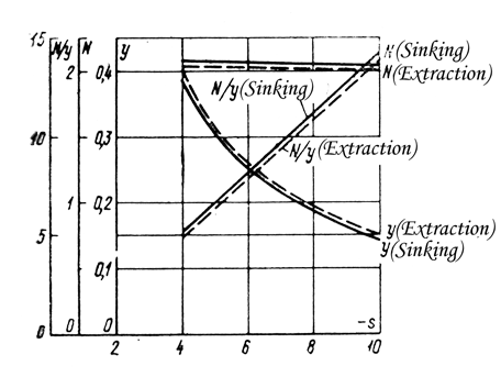
It was established by calculations that qualitatively the basic regularities of the impact-vibration extraction process correspond to the analogous regularities of impact-vibrational sinking (the dependences of y, N, N/y on ξ1, ξ2, λo, d and on the characteristics of the motor). At the same time, some quantitative differences are manifested between the data obtained in studying the processes of impact-vibrational sinking and extraction (Figure 40). In impact-vibrational extraction (in comparison with sinking) the displacement per impact is somewhat greater and the power required and the specific energy capacity of the process are less. At the same time, with a practically identical mean rotational speed of the eccentrics per cycle (0.9864 αH for sinking and 0.987 αH for extraction) the fluctuations in the angular velocity during sinking are greater than during extraction (amin = 0.9465 and amax = 1.024 during sinking, and αmin = 0.955 and αmax = 1.017 during extraction).
The area of existence of the “one impact for one revolution” regime for impact-vibrational sinking and extraction coincides completely for the calculation models, both those that take into account the nonuniformity of rotation of the eccentrics, and disregarding this characteristic.
The most economical mode of impact-vibrational driving and extraction, characterized by the parameters h = 0.4, ξ1 = 0.3 – 0.5, exists in practice only beginning with s = —2; at lesser resistances with respect to absolute value the regime becomes unstable, which leads to a sharp increase in the power required, an increase in the specific; energy capacity and a decrease in the efficiency of the process.
An analysis of the results of the calculations performed shows that some of the parameters of the vibrating hammer do not have a substantial influence on the power required. Thus, in the formulas for calculating the power it is possible to disregard the change in the ratio of the nominal moment of the motor imparted to the shaft of the eccentrics, and the static moment of the mass of the eccentrics.
The influence of the latter parameters is taken into account in the correlation formula below, presented in dimensionless form (G. G. Azbel and B. B. Rubin, 1983):
 ( 66 )
whence
![]() (67)
(67)
The power losses in overcoming friction in the bearings , movement of the oil, etc. can be calculated with the familiar formula
![]() (68)
(68)
where n is the nominal number of rotations of the eccentric shafts.
The power of the electric motor of the vibrating hammer NDB should be equal to the sum of two powers — the useful power M, expended in the driving or extraction of the elements, and that expended in overcoming resistance in the vibrating mechanism Npot.
Table 4. The results of comparing the power calculations with the data of the experimental studies
| Original Data Source | Calculated Data | Experimental data, Nexp , kW | |||||||||
| h | s | ξ1 | d |  | K, kg-cm | ω, 1/sec | N, kW | Npot, kW | NDB, kW | ||
| M. G. Tseitlin | 0.66 0.45 | 2 2 | 0.3 0.23 | 2.89 4.86 | 0.647 1.793 | 230 230 | 62.8 87.78 | 0.916 3.39 | 0.28 0.66 | 1.196 4.05 | 1.2 4.0 |
| V. V. Verstov and V. M. Lukin | 0.24 | 10 | 0.3 | 4.11 | 2.044 | 2500 | 62.8 | 31.5 | 5.9 | 37.4 | 37.1 |
| V. I. Chernyaev | 0.36 | 8 | 0.26 | 9.28 | 3.27 | 259 | 150.8 | 12.5 | 6.3 | 18.8 | 17.9 |
Table 4 compares the results of power calculations with formulas (65) and (67) with the data of experimental studies. as is evident from Table 4, formula (67) for determining the power of the electric motor of the vibrating hammer, expended in driving and extracting the elements, does not require preliminary calculations of the velocity at the time of impact and offers the possibility of calculating the motor power sufficiently precisely, which permits avoiding its overloading.
In performing the calculations with formulas (56), (58), (60), (62) and (63) the moment of the motor MDB and the acceleration xi (i = 1, 2) are calculated in each step of the integration, which provides the basis for plotting within the limits of period T the loading diagram of the moments and the diagram of the inertial forces acting in the direction of the x-axis.
The loading diagram of the moments makes it possible to perform the calculation on the stability and durability of the transmission elements of the vibrating hammer, and taking into account the variation in the value of the moment from the maximum to the minimum, the values of the inertial forces and a calculation of the durability of the shafts of the vibration exciter.
An equivalent load for selecting and verifying the service life of the oscillation bearings of the eccentric shafts can be determined from the diagram of the moments and the inertial forces, taking into account the action of the compelling force Po.
The body elements of the vibrating hammer construction can be calculated for stability and durability under the action of the inertial forces.


One thought on “Characteristics of the Dynamics of Vibration and Impact-Vibration Drivers”