
In addition to the cushion block size, another important input to the wave equation analysis is the size of the pipe cap (or anvil) block. Below are the basic dimensions for the pipe caps along with the depth of the steps.
|
HAMMER SIZE |
A | BDIA. | C | D | E | F° | GR. |
| 010 | 8 | 32 | 40 | 10 1/4 | 3 | – | – |
| 014, 016 | 10 | 39 | 53 3/4 | 10 1/4 | 3 | 29 | – |
| 016, 020, 030, 200C, 530 | 15 | 51 | 53 3/4 | 10 1/4 | 3 | 29 | – |
| 040, 340, 530, 540 | 18 1/2 | 75 | 80 | 14 | 4 | – | 6 |
| 060, 360, 560, 3100, 5110 | 24 | 75 | 87 1/2 | 18 1/4 | 4 | – | – |
| 5100 | 16 1/2 | 102 | 119 1/2 | 22 | 4 | – | – |
| 5150 | 19 1/2 | 102 | 119 1/2 | 22 | 4 | – | – |
| 126 | 143 1/2 | 22 | 4 | – | – | ||
| 6300 | 28 1/2 | 126 | 143 1/2 | 22 | 4 | – | – |
All dimensions in inches unless otherwise noted.
Note: Tip dated 1 September 1980. Dimensions in italics are for hammers introduced after that date. Subsequent to this Vulcan introduced its line of “Light Weight High Strength” pipe caps. The dimensions such as “A” were reduced and others such as “F” and “G” were eliminated altogether. It is important to determine whether the pipe cap being looked at conforms to the above dimensions or not. Also, many of Vulcan’s customers manufactured their own pipe caps, which may or may not conform to the dimensions shown in this tip.
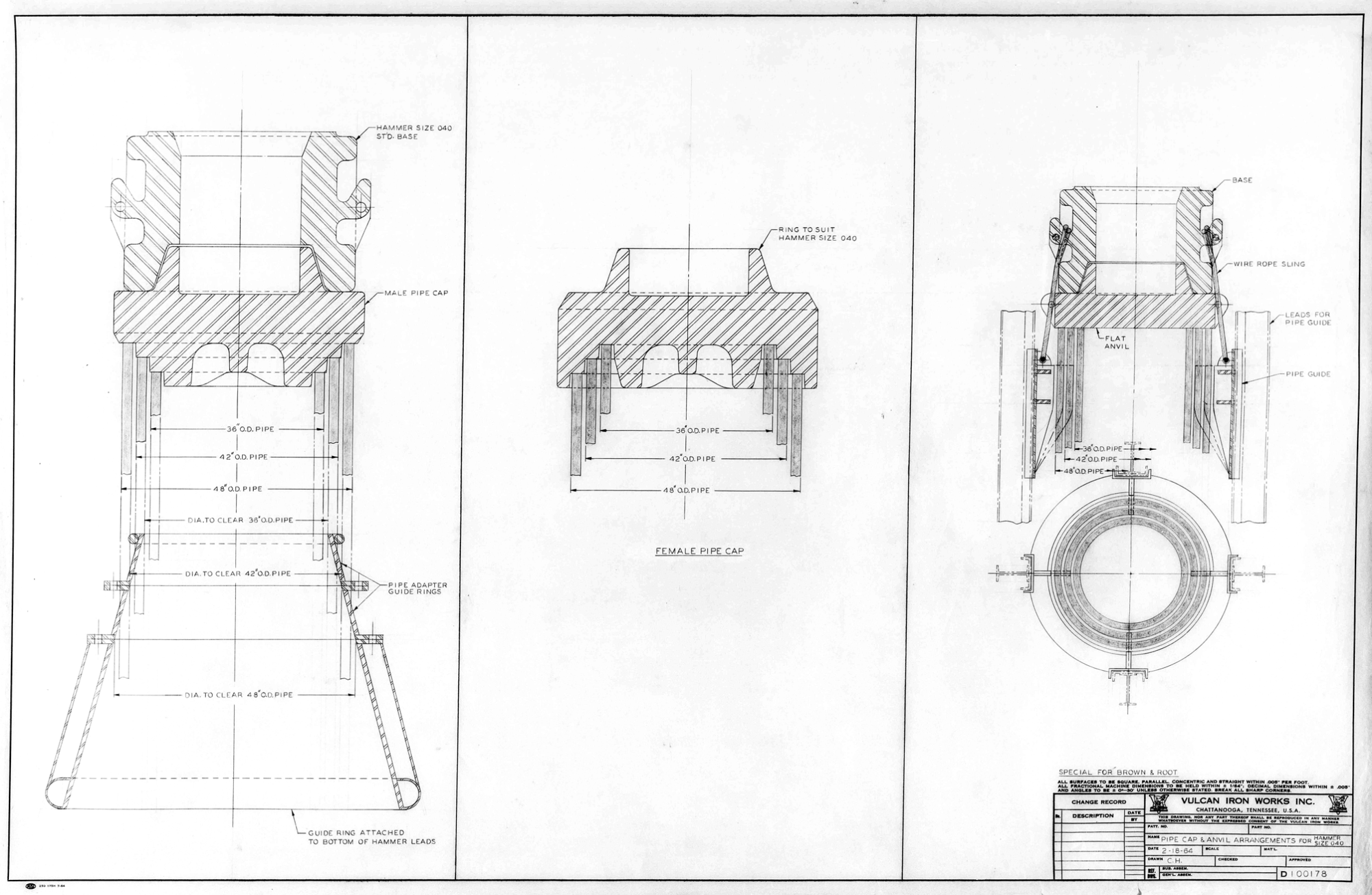
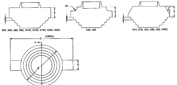
Vulcan’s choice of pipe cap design deserves some explanation. At the top is a diagram of the three basic types of pipe caps in use, both during the heyday of Vulcan offshore hammers and now.
- Male Caps (left) were the standard Vulcan configuration. The cap is stepped for different pipe sizes and is fitted to the I.D. of the pipe. To align the leads and the pile (especially important with the batter piles common offshore) the pipes were passed through a stabbing bell (at the bottom) which itself was stepped to the O.D. of the piles. The arrangement was preferred with Vulcan’s customers (especially those in the Gulf of Mexico) because the cap is easy to modify and shim for different size piles and the stabbing bell is easy for the crane operator to thread the hammer assembly over the pile for driving.
- Female Caps (centre) was most common with the Menck hammers. All of the steps were mated to the O.D. of the cap. Although mating it to piles was more straightforward, since the maximum plate moment of the cap was in the centre, the thicker centreline of the male cap was an advantage.
- Flat Face Caps (right) were preferred by the diesel manufacturers such as Delmag (and later IHC and Pileco.) Since there are no alignment steps on the cap, all of the alignment takes place with the adjustable keys under the cap facing the O.D. of the pile. (It’s better to have two sets of keys than the one shown.) Although the cap is much simpler, the carrier required for the cap and keys can be complicated to produce.


2 thoughts on “Vulcan Offshore Tip #21: Pipe Cap Dimensions”