
When you replace and install new studs In your Vulcan equipment, there are certain precautions to be observed.
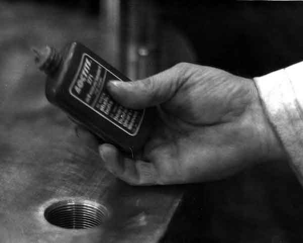
Prior to inserting studs, coat the threads with Loctite #271 to assure that studs will remain tight.
Tap End Studs and Vulcan Hammers
When most designers consider the use of threaded fasteners, they turn to nuts and bolts. Studs, however, appear on almost all Vulcan air/steam equipment. Although this looks antiquated at first, Vulcan had good reason to use studs in its higher load and more critical applications (cylinder heads, steam chest heads, etc.)
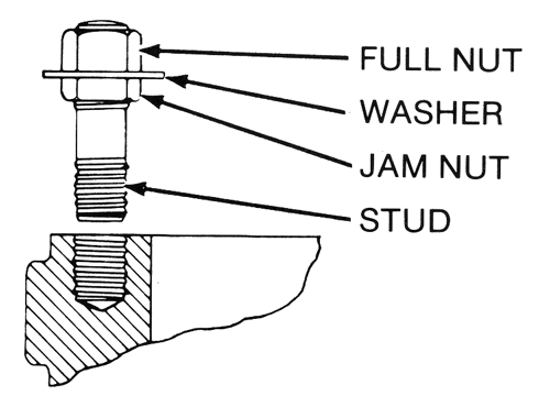
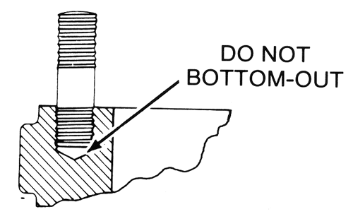
The studs Vulcan used were almost invariably what are referred to as “Tap-End Studs,” where one end of the stud was threaded into a blind tapped hole in a casting. The advantage of studs is twofold:
- The preload of any threaded fastener is always more accurate and consistent if the nut is torqued. It is generally necessary to add 20% or so to the torque applied to a bolt head because of the natural torsional twist of the bolt shank, and this factor can vary as well.
- The studs, once installed, can be used as guide dowels to assist assembly of parts.
Today most tap end studs used are in the oilfield, and there are appropriate (API and other) standards for their design. The following is taken from the American Machinists’ Handbook by Colvin and Stanley, Seventh Edition (1940). The parameters given in this reference are similar to the oilfield specs, but not identical.
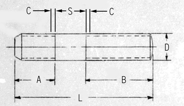
Dimensions
- D = nominal thread size (O.D.) of stud
- L = overall length of stud
- A = length of thread on tap end = D + 1/8″, and is measured from the end of the stud to the end of the imperfect thread
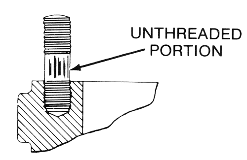
- S = length of the unthreaded portion or shoulder = D, except when L < 4D + 3/8″, in which case S may be decreased or eliminated entirely so that B > 2D + 1/4″.
- B = length of thread on the nut end = L – (A + S) > 2D + 1/4″, and is measured from the end of the stud to the end of the imperfect thread
- C = length of the imperfect threads < 2 1/2 threads
For short studs where S = 0, B can be less than 2D + 1/4″, but A > D + 1/8″.
If L > 4D + 3/8″, B = L – (A + S), or otherwise put, “the balance of the stud not consumed by A, the tap end threading (A = D + 1/8″) and S, the shoulder length (S = D).”
Note the convention of chamfering the tap end and rounding the nut end of the stud.
Application to Vulcan Hammers
Vulcan did not rigidly adhere to this convention, but adapted it to suit the clearance requirements of the mating parts, the thickness of the flange being fastened, etc. Vulcan was always conscious to maintain proper mating thread length on both ends. Vulcan studs incorporated either UNC or UNF threads.
Class 5 Interference Fits
The application of a tap end stud is supposed to include the use of “Class 5” interference fit threads. The idea behind this is the same as shrink fitting the studs to the base part.
Although Vulcan frequently specified Class 5 fits for the tap on its drawings, the actual result was not always a Class 5 tapped hole. This was because a) such a hole required a special tap, not always readily available (especially in field repair) and b) installing studs into Class 5 tapped holes was a difficult job. A more sensible solution (as shown in the Tip) was and is the use of Loctite, as shown at the top in a photo taken during the assembly of the 6300 hammers. Although Loctite has also been used to compensate for inadequate torquing, this is not proper procedure.


2 thoughts on “Vulcan Offshore Tip #12: Stud Installation”