
More Resources
- Foundation Design and Analysis: Deep Foundations, Lateral Loading of Piles
- Design and Construction of Driven Pile Foundations, 2016 Edition.
Having looked at axial loads on driven piles, we come to the subject of lateral loads on driven piles. Deep foundations in general are more suitable for lateral loads than shallow ones, so this topic is of importance in geotechnical engineering.
Overview

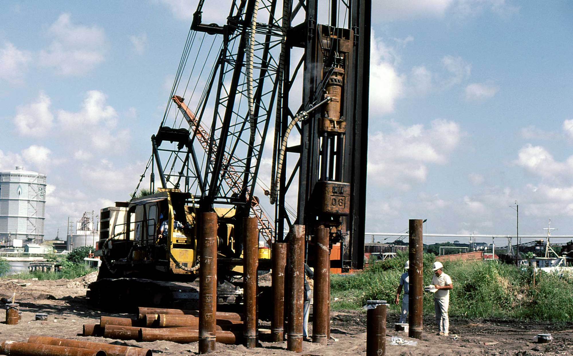
There are two ways that driven piles have been used for lateral loads, as shown on the right. The oldest are the raker (or more commonly called in the U.S. batter) piles. These piles are driven at an angle and basically turn a horizontal load into a primarily vertical one. These were used, for example, when Gaius Julius Caesar crossed the Rhine and built a bridge in ten (10) days. An example of how these piles can be driven is shown below. These are effective but they tend to be rigid, which makes them something of a liability in seismic events, where flexibility and the ability of the structure to withstand large deflections is crucial.

A newer approach is to drive these piles plumb (vertical) and treat them as a beam. This takes us into new territory, as we now have to consider moment of inertia, section modulus and the lateral stiffness of the soil resisting bending.
Short Piles: Broms’ Method

Laterally loaded piles can generally be divided into two types: piles which are short enough so that failure takes place primarily in the soil, and longer piles where failure can either be of the soil, the pile (excess bending moment and stresses) or both. This is illustrated at the left.
The problem of short piles was considered first. Below is a series of sketches of Broms’ Method, done by the man himself. A description of this method is given here, we will not deal with it further.


As a general rule the dividing line between “long” and “short” piles is this:
- Timber – D/B = 20
- Steel or Concrete – D/B = 35
Long Piles: the p-y Method
Turning to beam solutions, the first thought was to use beam with elastic foundation theory to model these piles. It became apparent that this would not work because of the non-linearity of the soils. Various methods were subsequently developed, but ultimately the best method developed was the p-y method. A nice summary of the early development of the method is here. The following is a brief overview.
Let’s start with considering how piles are loaded laterally and how they resist that load.

Piles are loaded at the head by horizontal shear forces, they can also be loaded with a moment. This can be done in two ways. The first is if the head is “free,” i.e., allowed to rotate, and the moment is imposed. The second is if the head is “fixed,” i.e., forced to be vertical or in line with the undeflected pile, and a moment results. For piles that are not groundline, i.e., the pile head and ground surface be some distance from each other, there can also be distributed lateral loads such as wind and water current on the pile. The soil resistance is nonlinear and resists the loads in like fashion. A diagram of this taking place is shown below.

The soil is modelled as a succession of “p-y curves,” which are horizontal deflection (y) vs. load (p) at a given point along the shaft of the pile. This is shown below.

Like the wave equation, though, it takes computer software to solve this problem. The software demonstrated here is COM624G; we offer a different version of that here. If you plan to do this for a living, the LPILE program is a further (and more user friendly) development of the same software. For this demonstration, we will have to change our example problem, because the p-y method is best suited for long piles, and for our example pile D/B = 30/1.5 = 20, which for a steel pile is considered short.
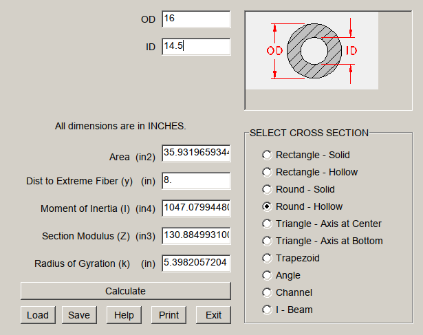
The example we’ll look at here is the second one from the COM624G manual. It involves a open-ended pipe pile which is 16″ in diameter and has a 3/4″ wall thickness from the pile head to 15′ below the pile head and 1/2″ down to the pile toe, the pile total length being 60′. The pile head is free (explained earlier.) It is subject to a lateral shear load of 10 kips and an axial load of 100 kips with no moment.) A handy tool to compute the areas and moment of inertia’s you’ll need here (and many other places) is Engineering Power Tools, which you can download here. The screenshots for the two pile segments are below.

The soil profile is as follows, the pile head is 5′ above the ground surface:
| Submerged Unit Weight, pcf | Layer Thickness, ft. | Cohesion, psf | Internal Friction Angle, degrees |
| 35 | 15 | 500 | 0 |
| 55 | 10 | 0 | 30 |
| 45 | 37 | 1000 | 0 |
The use of submerged unit weight below the water table (which is at the surface for this pile) is typical in the COM624 family of programs, and is one reason why I taught it in Soil Mechanics. Also typical is the use of inches, which is unusual for geotechnical applications (but not structural ones.)
The input is summarised by the program as follows, first graphically:

Noteworthy is the inclusion of the p-y curves at various elevations. The detailed text summary of the input data is below:
      ***** UNIT DATA. *****


    SYSTEM OF UNITS
    (UP TO 16 CHAR.)
 ENGL


      ***** PILE DATA. *****


   NO. INCREMENTS    NO. SEGMENTS     LENGTH  MODULUS OF    DEPTH
  PILE IS DIVIDED   WITH DIFFERENT      OF    ELASTICITY
                    CHARACTERISTICS    PILE
        120                2         .720E+03  .290E+08    .600E+02


   TOP OF    DIAMETER    MOMENT OF    CROSS-SECT.
  SEGMENT    OF PILE      INERTIA        AREA
  .000E+00   .160E+02     .105E+04      .359E+02
  .180E+03   .160E+02     .732E+03      .243E+02


      ***** SOIL DATA. *****


   NUMBER OF LAYERS
          3


 LAYER    P-Y CURVE    TOP OF   BOTTOM   INITIALSOIL   FACTOR  FACTOR
 NUMBER  CONTROL CODE  LAYER  OF LAYER  MODULI CONST.   'A'     'F'
 1         1        .600E+02  .240E+03   .300E+02     .000E+00  .000E+00
 2         4        .240E+03  .360E+03   .250E+02     .000E+00  .000E+00
 3         6        .360E+03  .800E+03   .100E+03     .100E+01  .700E+00


      ***** UNIT WEIGHT DATA. *****


 NO. POINTS FOR PLOT
 OF EFF. UNIT WEIGHT
     VS. DEPTH
           6


   DEPTH BELOW TOP     EFFECTIVE
       TO POINT       UNIT WEIGHT
       .600E+02         .200E-01
       .240E+03         .200E-01
       .240E+03         .320E-01
       .360E+03         .320E-01
       .360E+03         .260E-01
       .800E+03         .260E-01


      ***** PROFILE DATA. *****


  NO. POINTS FOR
 STRENGTH PARAMETERS
     VS. DEPTH
          6

   DEPTH BELOW   UNDRAINED SHEAR    ANGEL OF INTERNAL   STRAIN AT 50%
   TOP OF PILE   STRENGTH OF SOIL  FRICTION IN RADIANS   STRESS LEVEL
     .600E+02        .350E+01            .000E+00          .200E-01
     .240E+03        .350E+01            .000E+00          .200E-01
     .240E+03        .000E+00            .524E+00          .200E-01
     .360E+03        .000E+00            .524E+00          .200E-01
     .360E+03        .700E+01            .000E+00          .100E-01
     .800E+03        .700E+01            .000E+00          .100E-01


      ***** P-Y DATA. *****


     NO. OF
   P-Y CURVES
        0


      ***** OUTPUT DATA. *****


      DATA      OUTPUT       P-Y       NO. DEPTHS TO
    OUTPUT    INCREMENT    PRINTOUT      PRINT FOR
      CODE      CODE         CODE        P-Y CURVES
       1          2            1              8


   DEPTH FOR
   PRINTING
   P-Y CURVES
    .600E+02
    .800E+02
    .100E+03
    .150E+03
    .200E+03
    .250E+03
    .300E+03
    .500E+03


      ***** PILE HEAD (BOUNDARY) DATA. *****


   BOUNDARY     NO. OF SETS
   CONDITION    OF BOUNDARY
      CODE      CONDITIONS
       1             1


   PILE HEAD     LATERAL LOAD AT   VALUE OF SECOND     AXIAL LOAD
 PRINTOUT CODE     TOP OF PILE    BOUNDARY CONDITION    ON PILE
      1              .100E+05          .000E+00         .100E+06


      ***** CYCLIC DATA. *****


    CYCLIC(0)      NO. CYCLES
  OR STATIC(1)     OF LOADING
    LOADING
       0            .100E+03


      ***** PROGRAM CONTROL DATA. *****


  MAX. NO. OF   TOLERENCE ON    PILE HEAD DEFLECTION
   ITERATIONS     SOLUTION      FLAG (STOPS RUN)
                CONVERGENCE
      100         .100E-02            .240E+02
A graphical summary of the output data is here:

The distribution of lateral pressure on the pile, moment and deflection of the pile is shown above. Note that the moment at the pile head is zero; this is typical of free-head piles with no moment at the head. An estimate of the maximum bending stresses in the pile is left to the reader as an exercise. A summary of the results (including numerical tables of the p-y curves) is below.
GENERATED P-Y CURVES
THE NUMBER OF CURVES = 8
THE NUMBER OF POINTS ON EACH CURVE = 17
DEPTH DIAM C GAMMA E50
IN IN LBS/IN**2 LBS/IN**3
.00 16.000 .4E+01 .2E-01 .200E-01
Y,IN P,LBS/IN
.000 .000
.006 16.800
.200 52.917
.400 66.671
.600 76.319
.800 84.000
1.000 90.486
1.200 96.156
1.400 101.226
1.600 105.833
1.800 110.071
2.000 114.006
2.200 117.686
2.400 121.149
6.400 70.560
12.000 .000
16.000 .000
DEPTH DIAM C GAMMA E50
IN IN LBS/IN**2 LBS/IN**3
20.00 16.000 .4E+01 .2E-01 .200E-01
Y,IN P,LBS/IN
.000 .000
.006 20.940
.200 65.957
.400 83.100
.600 95.126
.800 104.700
1.000 112.785
1.200 119.852
1.400 126.171
1.600 131.914
1.800 137.196
2.000 142.100
2.200 146.687
2.400 151.004
6.400 95.688
12.000 18.577
16.000 18.577
DEPTH DIAM C GAMMA E50
IN IN LBS/IN**2 LBS/IN**3
40.00 16.000 .4E+01 .2E-01 .200E-01
Y,IN P,LBS/IN
.000 .000
.006 25.080
.200 78.997
.400 99.530
.600 113.933
.800 125.400
1.000 135.083
1.200 143.547
1.400 151.116
1.600 157.994
1.800 164.320
2.000 170.194
2.200 175.688
2.400 180.858
6.400 123.877
12.000 44.499
16.000 44.499
DEPTH DIAM C GAMMA E50
IN IN LBS/IN**2 LBS/IN**3
90.00 16.000 .4E+01 .2E-01 .200E-01
Y,IN P,LBS/IN
.000 .000
.006 35.430
.200 111.598
.400 140.604
.600 160.951
.800 177.150
1.000 190.829
1.200 202.786
1.400 213.478
1.600 223.195
1.800 232.132
2.000 240.430
2.200 248.191
2.400 255.495
6.400 207.740
12.000 141.442
16.000 141.442
DEPTH DIAM C GAMMA E50
IN IN LBS/IN**2 LBS/IN**3
140.00 16.000 .4E+01 .2E-01 .200E-01
Y,IN P,LBS/IN
.000 .000
.006 45.780
.200 144.198
.400 181.678
.600 207.969
.800 228.900
1.000 246.575
1.200 262.025
1.400 275.841
1.600 288.396
1.800 299.944
2.000 310.665
2.200 320.693
2.400 330.131
6.400 310.732
12.000 284.294
16.000 284.294
DEPTH DIAM PHI GAMMA A B PCT PCD
IN IN DEG LBS/IN**3
190.00 16.00 30.0 .2E-01 .88 .55 .16E+04 .18E+04
Y P
IN LBS/IN
.000 .000
.022 105.556
.044 211.111
.067 316.667
.089 422.222
.111 527.778
.133 627.427
.156 675.613
.178 720.334
.200 762.232
.222 801.772
.244 839.304
.267 875.100
.600 1400.160
5.733 1400.160
10.867 1400.160
16.000 1400.160
DEPTH DIAM PHI GAMMA A B PCT PCD
IN IN DEG LBS/IN**3
240.00 16.00 30.0 .2E-01 .88 .55 .28E+04 .25E+04
Y P
IN LBS/IN
.000 .000
.022 133.333
.044 266.667
.067 400.000
.089 533.333
.111 666.667
.133 800.000
.156 933.333
.178 1066.667
.200 1200.000
.222 1279.319
.244 1339.206
.267 1396.323
.600 2234.117
5.733 2234.117
10.867 2234.117
16.000 2234.117
DEPTH DIAM C CAVG GAMMA E50
IN IN LBS/IN**2 LBS/IN**3 LBS/IN**3
440.00 16.000 .7E+01 .4E+01 .3E-01 .100E-01
Y P
IN LBS/IN
.000 .000
.013 220.142
.027 277.362
.040 317.500
.053 349.454
.067 376.438
.080 400.025
.093 421.117
.107 440.285
.120 457.914
.133 474.282
.147 489.592
.160 504.000
1.173 504.000
2.187 504.000
3.200 504.000
4.800 504.000
EX. PRO. 2 FROM DOCUMENTATION OF COM. PRO. COM624 BY L.C. REESE, 1980.
UNITS--ENGL
O U T P U T I N F O R M A T I O N
***********************************
NO. OF ITERATIONS = 14
MAXIMUM DEFLECTION ERROR = .562E-03 IN
PILE LOADING CONDITION
LATERAL LOAD AT PILE HEAD = .100E+05 LBS
APPLIED MOMENT AT PILE HEAD = .000E+00 LBS-IN
AXIAL LOAD AT PILE HEAD = .100E+06 LBS
X DEFLEC MOMENT TOTAL DISTR. SOIL FLEXURAL
STRESS LOAD MODULUS RIGIDITY
IN IN LBS-IN LBS/IN**2 LBS/IN LBS/IN**2 LBS-IN**2
******* ********* ********* ********* ********* ********* *********
.00 .135E+01 .000E+00 .278E+04 .000E+00 .000E+00 .304E+11
12.00 .125E+01 .130E+06 .378E+04 .000E+00 .000E+00 .304E+11
24.00 .115E+01 .260E+06 .477E+04 .000E+00 .000E+00 .304E+11
36.00 .105E+01 .390E+06 .576E+04 .000E+00 .000E+00 .304E+11
48.00 .954E+00 .520E+06 .676E+04 .000E+00 .000E+00 .304E+11
60.00 .859E+00 .649E+06 .774E+04 .000E+00 .100E+03 .304E+11
72.00 .767E+00 .769E+06 .866E+04 .000E+00 .124E+03 .304E+11
84.00 .679E+00 .875E+06 .947E+04 .000E+00 .152E+03 .304E+11
96.00 .595E+00 .965E+06 .102E+05 .000E+00 .185E+03 .304E+11
108.00 .515E+00 .104E+07 .107E+05 .000E+00 .224E+03 .304E+11
120.00 .441E+00 .110E+07 .112E+05 .000E+00 .272E+03 .304E+11
132.00 .371E+00 .114E+07 .115E+05 .000E+00 .331E+03 .304E+11
144.00 .307E+00 .116E+07 .116E+05 .000E+00 .405E+03 .304E+11
156.00 .249E+00 .116E+07 .116E+05 .000E+00 .500E+03 .304E+11
168.00 .196E+00 .114E+07 .115E+05 .000E+00 .626E+03 .304E+11
180.00 .148E+00 .111E+07 .162E+05 .000E+00 .802E+03 .258E+11
192.00 .107E+00 .106E+07 .157E+05 .000E+00 .106E+04 .212E+11
204.00 .726E-01 .989E+06 .149E+05 .000E+00 .144E+04 .212E+11
216.00 .452E-01 .905E+06 .140E+05 .000E+00 .209E+04 .212E+11
228.00 .239E-01 .806E+06 .129E+05 .000E+00 .328E+04 .212E+11
240.00 .800E-02 .696E+06 .117E+05 .000E+00 .450E+04 .212E+11
252.00 -.314E-02 .580E+06 .104E+05 .000E+00 .480E+04 .212E+11
264.00 -.103E-01 .466E+06 .919E+04 .000E+00 .510E+04 .212E+11
276.00 -.144E-01 .358E+06 .802E+04 .000E+00 .540E+04 .212E+11
288.00 -.160E-01 .262E+06 .697E+04 .000E+00 .570E+04 .212E+11
300.00 -.158E-01 .178E+06 .605E+04 .000E+00 .600E+04 .212E+11
312.00 -.144E-01 .108E+06 .529E+04 .000E+00 .630E+04 .212E+11
324.00 -.123E-01 .510E+05 .466E+04 .000E+00 .660E+04 .212E+11
336.00 -.983E-02 .549E+04 .417E+04 .000E+00 .690E+04 .212E+11
348.00 -.732E-02 -.303E+05 .444E+04 .000E+00 .720E+04 .212E+11
360.00 -.500E-02 -.584E+05 .475E+04 .000E+00 .300E+05 .212E+11
372.00 -.307E-02 -.697E+05 .487E+04 .000E+00 .312E+05 .212E+11
384.00 -.161E-02 -.671E+05 .484E+04 .000E+00 .324E+05 .212E+11
396.00 -.595E-03 -.568E+05 .473E+04 .000E+00 .336E+05 .212E+11
408.00 .314E-04 -.435E+05 .458E+04 .000E+00 .348E+05 .212E+11
420.00 .363E-03 -.303E+05 .444E+04 .000E+00 .360E+05 .212E+11
432.00 .488E-03 -.188E+05 .431E+04 .000E+00 .372E+05 .212E+11
444.00 .484E-03 -.996E+04 .422E+04 .000E+00 .384E+05 .212E+11
456.00 .411E-03 -.372E+04 .415E+04 .000E+00 .396E+05 .212E+11
468.00 .312E-03 .187E+03 .411E+04 .000E+00 .408E+05 .212E+11
480.00 .214E-03 .227E+04 .413E+04 .000E+00 .420E+05 .212E+11
492.00 .130E-03 .305E+04 .414E+04 .000E+00 .432E+05 .212E+11
504.00 .667E-04 .301E+04 .414E+04 .000E+00 .444E+05 .212E+11
516.00 .237E-04 .254E+04 .413E+04 .000E+00 .456E+05 .212E+11
528.00 -.218E-05 .191E+04 .413E+04 .000E+00 .468E+05 .212E+11
540.00 -.151E-04 .128E+04 .412E+04 .000E+00 .480E+05 .212E+11
552.00 -.193E-04 .753E+03 .412E+04 .000E+00 .492E+05 .212E+11
564.00 -.183E-04 .361E+03 .411E+04 .000E+00 .504E+05 .212E+11
576.00 -.149E-04 .998E+02 .411E+04 .000E+00 .516E+05 .212E+11
588.00 -.107E-04 -.509E+02 .411E+04 .000E+00 .528E+05 .212E+11
600.00 -.682E-05 -.120E+03 .411E+04 .000E+00 .540E+05 .212E+11
612.00 -.373E-05 -.136E+03 .411E+04 .000E+00 .552E+05 .212E+11
624.00 -.156E-05 -.122E+03 .411E+04 .000E+00 .564E+05 .212E+11
636.00 -.203E-06 -.944E+02 .411E+04 .000E+00 .576E+05 .212E+11
648.00 .511E-06 -.649E+02 .411E+04 .000E+00 .588E+05 .212E+11
660.00 .783E-06 -.395E+02 .411E+04 .000E+00 .600E+05 .212E+11
672.00 .785E-06 -.207E+02 .411E+04 .000E+00 .612E+05 .212E+11
684.00 .642E-06 -.874E+01 .411E+04 .000E+00 .624E+05 .212E+11
696.00 .438E-06 -.249E+01 .411E+04 .000E+00 .636E+05 .212E+11
708.00 .216E-06 -.243E+00 .411E+04 .000E+00 .648E+05 .212E+11
720.00 -.931E-08 .000E+00 .411E+04 .000E+00 .660E+05 .212E+11
OUTPUT VERIFICATION
THE MAXIMUM MOMENT IMBALANCE FOR ANY ELEMENT = .600E-01 IN-LBS
THE MAX. LATERAL FORCE IMBALANCE FOR ANY ELEMENT = -.873E-02 LBS
COMPUTED LATERAL FORCE AT PILE HEAD = .10000E+05 LBS
COMPUTED MOMENT AT PILE HEAD = .00000E+00 IN-LBS
COMPUTED SLOPE AT PILE HEAD = -.84314E-02
THE OVERALL MOMENT IMBALANCE = .118E-01 IN-LBS
THE OVERALL LATERAL FORCE IMBALANCE = -.330E-07 LBS
OUTPUT SUMMARY
PILE HEAD DEFLECTION = .135E+01 IN
MAXIMUM BENDING MOMENT = .116E+07 IN-LBS
MAXIMUM TOTAL STRESS = .162E+05 LBS/IN**2
MAXIMUM SHEAR FORCE = .108E+05 LBS
EX. PRO. 2 FROM DOCUMENTATION OF COM. PRO. COM624 BY L.C. REESE, 1980.
S U M M A R Y T A B L E
*************************
LATERAL BOUNDARY AXIAL MAX. MAX.
LOAD CONDITION LOAD YT ST MOMENT STRESS
(LBS) BC2 (LBS) (IN) (IN/IN) (IN-LBS) (LBS/IN**2)
.100E+05 .000E+00 .100E+06 .135E+01 -.843E-02 .116E+07 .162E+05
Long Piles: CLM 2.0
With a version of COM624/LPILE not readily available for academic use, one alternative is to use CLM (Characteristic Load Method,) a spreadsheet distillation of COM624 developed at Virginia Tech in the early 2000’s. You can download both the spreadsheet and documentation for this here, which also explains the theory. Here some results for this problem will be presented.
I say “some results” because CLM 2.0 makes some assumptions (in addition to simplifying the soil response) which are not really true for this pile and many others:
- The pile has a uniform cross-section.
- The soil is uniform.
- The pile is groundline, which means the pile head and ground surface are the same.
- There is no axial load on the pile.
To use CLM 2.0 we will a) use the top cross-section of the pile, b) the soil properties at the topmost layer, c) ignore the gap between the pile head and the soil surface and d) ignore the axial load problem.
All that said, the input for the software looks like this:
| INPUT PARAMETERS | |||
| UNITS | |||
| FORCE = | POUNDS | ||
| LENGTH = | IN | ||
| SOIL PROPERTIES | |||
| Su = | 3.500 | POUNDS/IN^2 | |
| PILE PROPERTIES | |||
| Do = | 16 | IN | |
| Di = | 14.50 | IN | |
| I = | 0 | IN^4 | |
| Rcr = | 1 | ||
| Ep = | 29000000 | POUNDS/IN^2 | |
| L = | 720 | IN | |
| PILE GROUP PROPERTIES | |||
| Nrow = | 30 | ||
| S/D = | 3 | ||
The variables are as follows:
| Su = | Undrained shear strength for clay |
| f = | Effective friction angle for sand |
| g = | Effective unit weight for sand |
| Do = | Outside pile diameter (circular) or width (noncircular) |
| Di = | Inside diameter of pipe pile |
| [enter zero for solid section] | |
| I = | Moment of inertia for any noncircluar section |
| [enter zero for circular section] | |
| Rcr = | Ratio of cracked EI to uncracked EI |
| Ep = | Modulus of elasticity of pile or drilled shaft |
| L = | Length of pile or drilled shaft |
| Nrow = | Number of rows in pile group |
| S/D = | Pile spacing to diameter ratio |
| Fm = | Group efficiency |
The parameters that result are as follows:
| CALCULATED PILE PARAMETERS | ||||
| Icirc= | 3216.99 | IN^4 ( I for solid circle) | ||
| Ri = | 0.33 | ( I / Icirc) | ||
| EpRi = | 9439044.00 | POUNDS/IN^2 | ||
| EpRi/Su = | 2,696,870 | |||
| L/D = | 45 | |||
| CHARACTERISTIC LOAD AND MOMENT | ||||
| Pc = | 751414.0 | POUNDS | ||
| Mc = | 164315933.6 | IN-POUNDS | ||
| CALCULATED P-MULTIPLIER | ||||
| Fm = | 0.52 | |||
| MINIMUM REQUIRED L/D FOR CLM | ||||
| EpRi/Su | 100,000 | 300,000 | 1,000,000 | 3,000,000 |
| L/D | 6 | 10 | 14 | 18 |
The L/D is obviously suitable for CLM 2.0. The output for the free head condition is as follows:
| Pt | Pt/Pc | Yt/D | Yp | Mmax |
| POUNDS | IN | IN-POUNDS | ||
| per Pile | ||||
| 2000.0 | 0.0027 | 0.0010 | 0.016 | 67801.6 |
| 4000.0 | 0.0053 | 0.0036 | 0.058 | 165564.3 |
| 6000.0 | 0.0080 | 0.0075 | 0.121 | 279107.9 |
| 8000.0 | 0.0106 | 0.0127 | 0.204 | 404290.2 |
| 10000.0 | 0.0133 | 0.0191 | 0.306 | 538906.4 |
Both the maximum moment and the head deflection are below those computed by COM 624G. This illustrates the weakness of the solution: there are too many simplifying assumptions. Although it is useful to some extent as a teaching tool, it is unsatisfactory for use in practice, as this report indicates.


2 thoughts on “Driven Pile Design: Lateral Loads on Piles”