
The basic mechanics of vibratory pile drivers, i.e., those which drive with vibration and without impact, are well documented. This is a more detailed look at their kinematics (and some of their kinetics) which will show, at the least, that these aren’t just pulled out of the air but have some basis in the dynamics of the system.
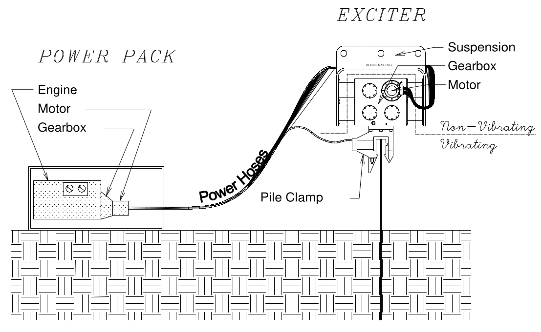
The basic setup of a vibratory driver is shown above. We will concentrate on the eccentrics, which are shown below.
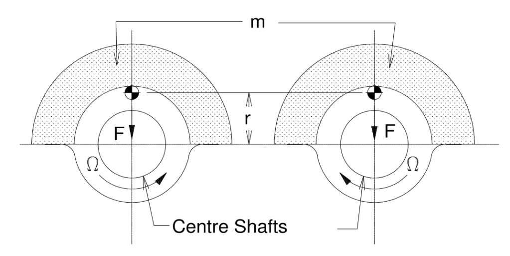
The vibratory eccentrics are made up of counterrotating pairs with an eccentric mass m (which can also be expressed as a weight) whose centroid is a distance r from the centre shaft, which is the centre of rotation. (Note that the centroid in this case is outside of the mass of the eccentric, which is not uncommon with centroids.) At this point we will make two important assumptions:
- The rotation of the eccentrics has a uniform angular velocity ω, expressed in radians/second. A rough rule of thumb is that 10 revolutions per minute (RPM) is equal to 1 radian/second, which means that it’s just another way to measure the rotational speed of the eccentrics. Non-uniformity of angular velocity does exist and is discussed on a theoretical basis here.
- The centre shafts have no horizontal or vertical motion. This may seem odd but it is an important assumption to determine the basic motion of the eccentrics.
The Kinematics
With those out of the way, we can express the vector expression of the position of the centroid as a function of time, thus

where r(t) is the vector quantity of position as a function of time.
The velocity of the centroid is the vector derivative of the position,

The acceleration of the centroid is again the derivative of the velocity,

At this point it’s time for dot products. Why dot products? Because they enable us to compute the scalar magnitude of various quantities in directions other than the Cartesian axes. (An example of the use of the dot product is here.) Since the eccentrics are continuously rotating, the importance of this should be evident. Let us begin by considering the acceleration of the centroid in the direction of the position and velocity. We need the unit vectors for these quantities, first the position:

and then the velocity:
If we take the dot product of Equations (4) and (3), we have

The dot product of Equations (5) and (3) is

Equation (6) shows that, in the direction of the velocity, the acceleration is zero. We should expect this, as the angular velocity is uniform. The surprise comes in Equation (5); even though the angular velocity is uniform, because of the curvature of the motion there is angular acceleration, in this case pointing towards the centre of rotation. This ultimately furnishes the vibratory force which drives piling.
Comparison of Equations (5) and (2) should show that the scalar velocity tangent to the path of motion is

Since the radius of motion r is constant, the velocity of the centroid normal to the path of motion is zero.
Let us take an example, in this case the Vulcan 1400 vibratory driver. The basic data is as follows:
- Radius of eccentric weight r = 3.827”
- Rotational Speed ω = 2400 RPM ~ 240 rad/sec (using the rough rule of thumb shown above)
Making substitutions yields the following:
- Displacement = 3.827*(cos(240t)i + sin(240t)j
- Velocity = -(3.827)(240)((sin(240t)i – cos(240t)j)
- Acceleration = -(3.827)(240)2(cos(240t)i + sin(240t)j)
- Tangential Velocity = (3.827”)(240 rad/sec) = 918.48 in/sec = 76.54 ft/sec
- Radial acceleration = -(3.827”)(240 rad/sec)2 = 220,435.2 in/sec2 = 18369.6 ft/sec2 = 570.5 g’s
Those who are familiar with impact pile driving will note that the tangential velocity of the centroid and the radial acceleration of the eccentrics exceed both the impact velocity of most impact hammers and the impact deceleration of most impact rams. Although this is in reality a “high speed” vibratory driver, the idea that vibratory driving is a “soft” form of pile driving relative to the equipment is simply not the case.
The Kinetics
None of this is very useful unless it is related to the dynamic force of the eccentrics. This is a breakdown of how this force is computed.
The motion we’re looking at here is purely rotational, which means that only the acceleration normal to the rotation (toward the centre of the shafts) is of interest. This is given by Equation (5). Since the acceleration is depicted as toward the centre of the shaft, students (including this one) have found this confusing, as we instinctively know that, left to itself, the eccentric would fly away from the shaft, just as a car going too fast on an inadequately banked roadway will leave the road on the outside of the radius. (Since this is a geotechnically oriented site, we feel free to take gratuitous potshots at the transportation people.)
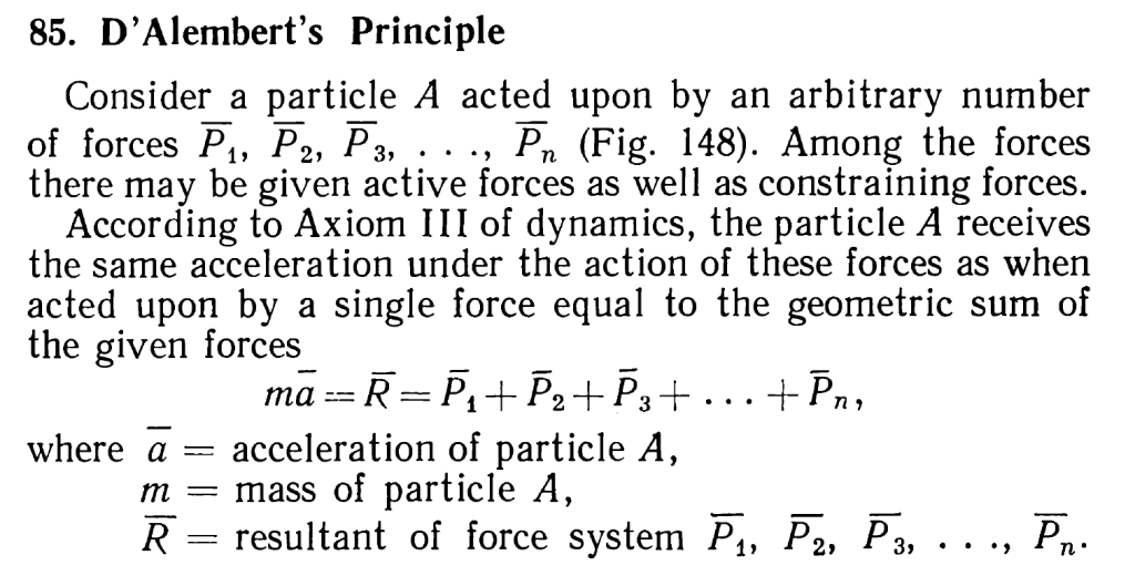
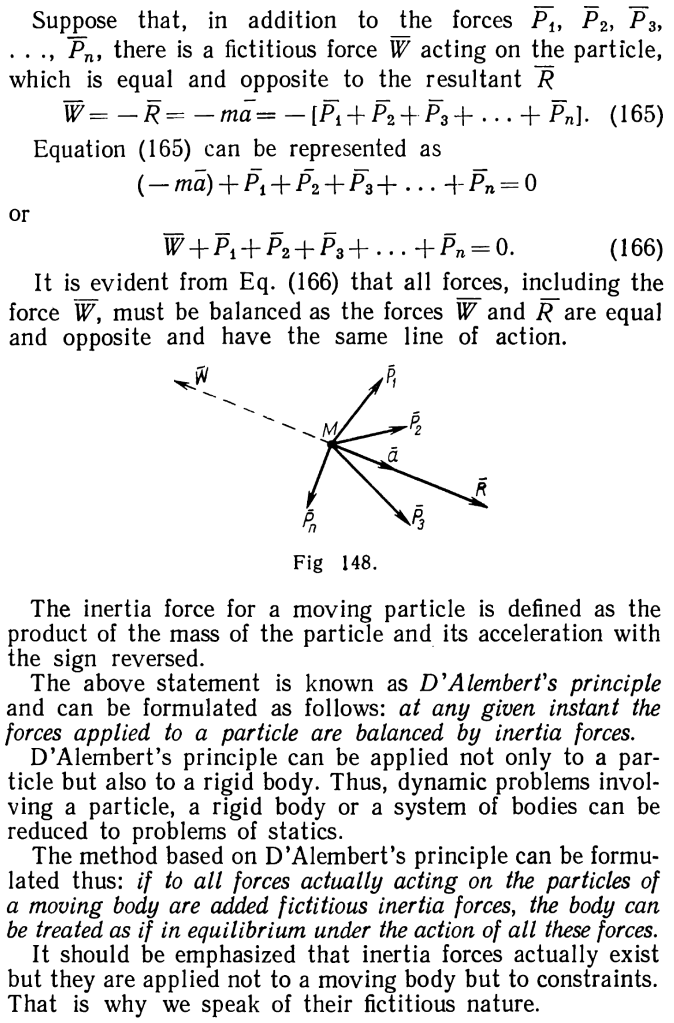
One way to clear up the confusion is to invoke d’Alembert’s Principle. This the same d’Alembert who came up with the most commonly used solution of the undamped wave equation and caused a real “brown pants moment” with d’Alembert’s Paradox. In any case this is done in Movnin and Izrayelit, and is shown below:
We can formulate the forces on the eccentrics thus:

The dynamic force F is the only constraining force (indeed, the only force of any kind) acting on the eccentrics. The force W is the radial/normal acceleration force, given by Newton’s Law as

where m is the eccentric mass. Substituting Equation (9) into Equation (8) and solving yields

Since, in the industry, we customarily define the eccentric moment as

we have at last

Since the eccentric weight for each eccentric is 92.7 lbs., the mass for each (in U.S. Units) is 92.7/32.2 = 2.88 slugs. Substituting into Equation (10), the dynamic force F = 52,884 lbs.. For a pair of eccentrics (the 1400 had only one pair,) the dynamic force would be 52.9 U.S. tons, which is a little above the 50 ton rating of the machine.
This approach makes sense in the SI system. For the U.S. system, there’s an easier way. We noted that the radial/normal acceleration of the eccentrics is 570.5 g’s. Since we are neglecting the effects of gravity, this is the entire acceleration, and thus the inertial force of the eccentrics is the product of the acceleration in g’s with the eccentric weight. Since Wecc = mgc, put more formally, this means that

We see that the gc‘s cancel out and we have the same result as Equation (10).
In any case, using the approach the dynamic force of each eccentric the dynamic force is (92.7)(570.5) = 52,884 lbs = 26.4 U.S. tons. Since there are two eccentrics, the total dynamic force is 52.9 tons, as before.
This approach can also be used with Those Pesky Kilogram-Force Units…


5 thoughts on “The Kinematics and Kinetics of Vibratory Driver Eccentric Rotation”