
For the rest of the book click here.
Currently, several methods are known for trenchless pipe laying: puncture – pressing closed pipes, punching with simultaneous development and removal of soil from the pipe and horizontal drilling.
For trenchless installation of pipes with a diameter of up to 500 mm, used as casings for laying pipelines and cable lines at crossings under roads, the puncture method is usually used. In this case, screw or hydraulic jacks, winches with pulleys or tractors are used, with the help of which the pipes are pressed into the ground. The advantage of this method is that there is no need to develop and remove soil from the pipe. Since large static forces, measured in tens and hundreds of tons, are required to overcome soil resistance, when performing work using the puncture method, it is necessary to erect expensive powerful thrust walls or anchors to absorb reactive forces from jacks or pulleys. The attainable speeds for pressing pipes into the ground are relatively small and usually do not exceed 2-4 m/hour, and the time required to perform auxiliary operations is large. The consequence of this is low labor productivity.
A significant reduction in soil resistance forces and an increase in the speed of pressing pipes into it can be achieved by using vibration.
This possibility has been noticed for a long time, in connection with the successful development of the method of vibration driving of sheet piles, piles and pipes. However, the first studies and experimental work on the use of vibration for trenchless pipe laying, carried out by various organizations, were not successful. In these works, an attempt was made to use high-frequency non-directional vibrators that cause circular vibrations of the head of a pipe or a special unit in a plane perpendicular to the axis of the penetration. Meanwhile, as experiments have shown, non-directional vibrations do not contribute to overcoming the drag of the soil, which can be very large. Moreover, in non-cohesive soils, such vibrations can even cause an increase in soil resistance due to its compaction ahead of the pipe being laid.
In 1958, VNIIGS developed a new method for trenchless laying of pipes with a diameter of up to 500 mm using vibration puncture. A distinctive feature of the method is the vibration of the pipe being pressed or its tip, directed along the axis of the penetration.
As can be seen from Fig. 114, for trenchless pipe laying, three schemes for using directed longitudinal vibrations can be used.
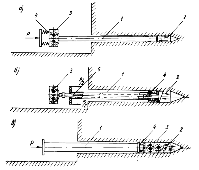
In the first scheme (Fig. 114a), pipe 1 is rigidly connected to tip 2 and directional vibrator 3. The pressing force P is transmitted to the vibrator and the pipe through a system of springs 4. In the second scheme (Fig. 114b), pipe 1 is not subject to vibration. The tip 2, the diameter of which exceeds the diameter of the pipe, is connected to the vibrator 3 by means of tubular rods 5, and the pressing force P is applied to the pipe being laid and is transmitted to the tip through a system of springs 4. In the third scheme (Fig. 114c), a directional vibrator 3 is mounted in a tip 2, to which, as in the second scheme, the pressing force is transmitted through the laid pipe 1 and a system of springs 4.
In these schemes, longitudinal vibrations of the tip, similar to what occurs during vibration driving of piles, destroy the soil structure and at the same time significantly reduce the friction forces on the lateral surface. As a result of this effect on the ground, it is possible to lay pipes with relatively little effort at a much higher speed than with conventional indentation. As preliminary studies show, the crushing force during vibration puncture can be 8-10 times less, and the pushing speed is 6-8 times higher than with a regular puncture with jacks.
For laying pipes using the vibration puncture method, a pilot installation has been created at VNIIGS (Fig. 115), which consists of a guide frame 1, a trolley 2, a directional vibrator 3 and a winch 4. The cable from the winch is connected to the trolley and the guide frame by a double-sided pulley 5, and the trolley with vibrator – spring system 6. The rotation of the shafts with the vibrator unbalances is carried out by an electric motor 7 via a V-belt drive. At the bottom, the vibrator rests on the trolley through a roller device 8.
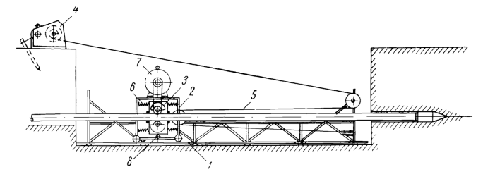
The vibration installation of the type under consideration is suitable for laying pipes according to the first scheme (Fig. 114a). It works as follows:
After preparing the pit, a guide frame and a trolley with a vibrator are lowered into it. Then the pipe to be laid is inserted into the vibrator, pre-welded for the entire length of the transition or for most of it. A pipe equipped with a tip is pushed into the vibrator so that the tip rests against the front wall of the pit, and the cart with the vibrator is placed in the rearmost position. After this, the vibrator is secured to the pipe, the electric motor and winch are turned on, and excavation begins. During normal operation of the installation, the trolley with the electric motor does not participate in vibrations, since they are connected to the vibrator by a system of springs.
When the trolley reaches the front edge of the frame, the winch and vibrator are turned off, the pipe is released, the trolley is moved again to the rearmost position and the cycle of work is repeated. After the pipe is pressed into the ground, it is welded with the next pipe and the penetration continues until the tip exits the receiving pit.
This scheme of work is very rational for laying relatively light pipes weighing up to 1 ton using low-power vibrators.
When laying heavier pipes, powerful vibrators are required to obtain a sufficiently large amplitude of pipe vibration. In this case, it is more rational to use vibration puncture with transmission of vibrations to the tip through tubular rods (Fig. 114b). For this, the same vibration installation can be used, but equipped with a device for transmitting force to the pipe being pressed. A spring system must be installed between the pipe and the tip.
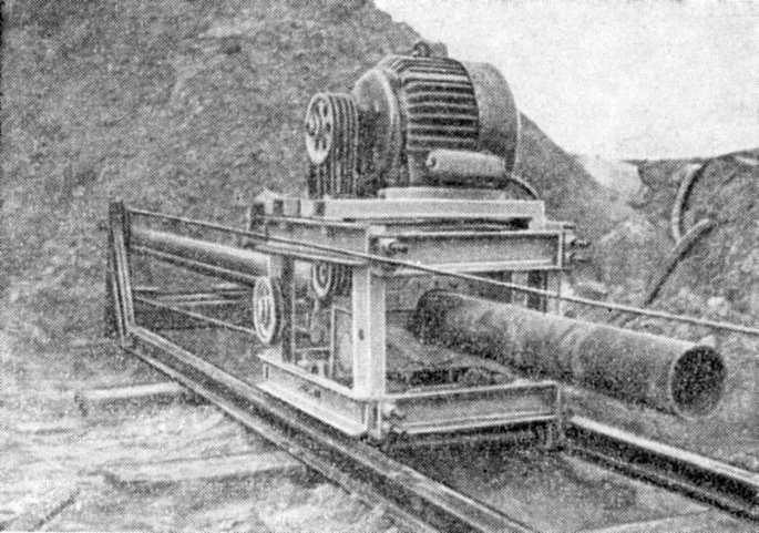
VNIIGS manufactured and tested under production conditions the first sample of a UVP-l type installation (Fig. 116) for trenchless installation using vibration puncture of pipes with a diameter of up to 200 mm for a length of 25-30 m.* The installation has the following technical characteristics:
| Electric motor power | 7 kW |
| Static moment of the eccentrics | 40-160 kg-cm |
| Vibration frequency | 1000-2000 RPM |
| Largest amplitude of the disturbing force | 7.1 tons |
| Winch lifting capacity | 0.75 tons |
| Weight of the vibrator with the trolley | 630 kg |
| Frame guide weight | 480 kg |
*During development of the installation drawings and production tests, engineer G. A. Melnik and technician L. V. Ilyin took part.
During production tests of the UVP-l type installation, 15 pipes with a diameter of 112-152 mm were laid for a length of up to 22 m. The laying of pipes (Fig. 117) was carried out using a manual winch with a lifting capacity of about 0.75 m. The average penetration rate was 0.5-0.7 m/min. On average, it took 4-6 hours to lay one pipe, including all auxiliary operations, except for excavating pits. Production tests have shown the good performance of this installation, which allows it to be widely used.

Vibrating installations of this type can not only lay pipes in the ground, but also easily remove them from the ground. This possibility has been verified many times in production tests. This means that using the method under consideration, it is possible to construct short-length transitions from steel pipes with external anti-corrosion insulation or non-metallic pipes with low mechanical strength (asbestos-cement, ceramic, plastic, etc.), the trenchless installation of which is practically impossible using the usual pressing method.
The laying of such pipes, depending on the quality and condition of the soil, can be carried out in one of two ways: in stable soils, using a vibration installation and tubular rods, you can push a tip of the appropriate diameter along the entire length of the transition, then remove it by vibration and at the same time insert it from the side of the receiving pit pipes laid into the resulting well with smooth, compacted walls. To insert pipes, you can use a traction force to remove the tip.
In unstable, weak soils, the walls of the well will collapse. Therefore, first, a temporary steel pipe covered with a tip is pushed through, then in the receiving pit the tip is removed and a non-metallic or insulated pipe is laid inside the pipe. After this, the outer pipe is removed from the ground by vibration, creating a stop for the inner pipeline.
Currently, VNIIGS has developed a project for a more powerful installation UVP-2, designed for laying pipes with a diameter of up to 400 mm using vibration puncture. The technical characteristics of this installation are as follows:
| Electric motor power | 28 kW |
| Static Eccentric Moment (adjustable) | Up to 2000 kg-cm |
| Vibration frequency | 1000-1200 RPM |
| Maximum dynamic force | 32 tons |
| Winch lifting capacity | 3 tons |
| Weight of the vibrator with the trolley | 2.4 tons |
| Guide frame weight | 1.1 tons |
In the future, it is planned to create a vibration installation for laying pipes with a diameter of 400-500 mm using a downhole type directional vibrator, which will be the most compact and convenient to operate, while at the same time maintaining all the advantages of installations of the type considered.


One thought on “Use of Vibratory Hammers for Trenchless Pipe Laying”