
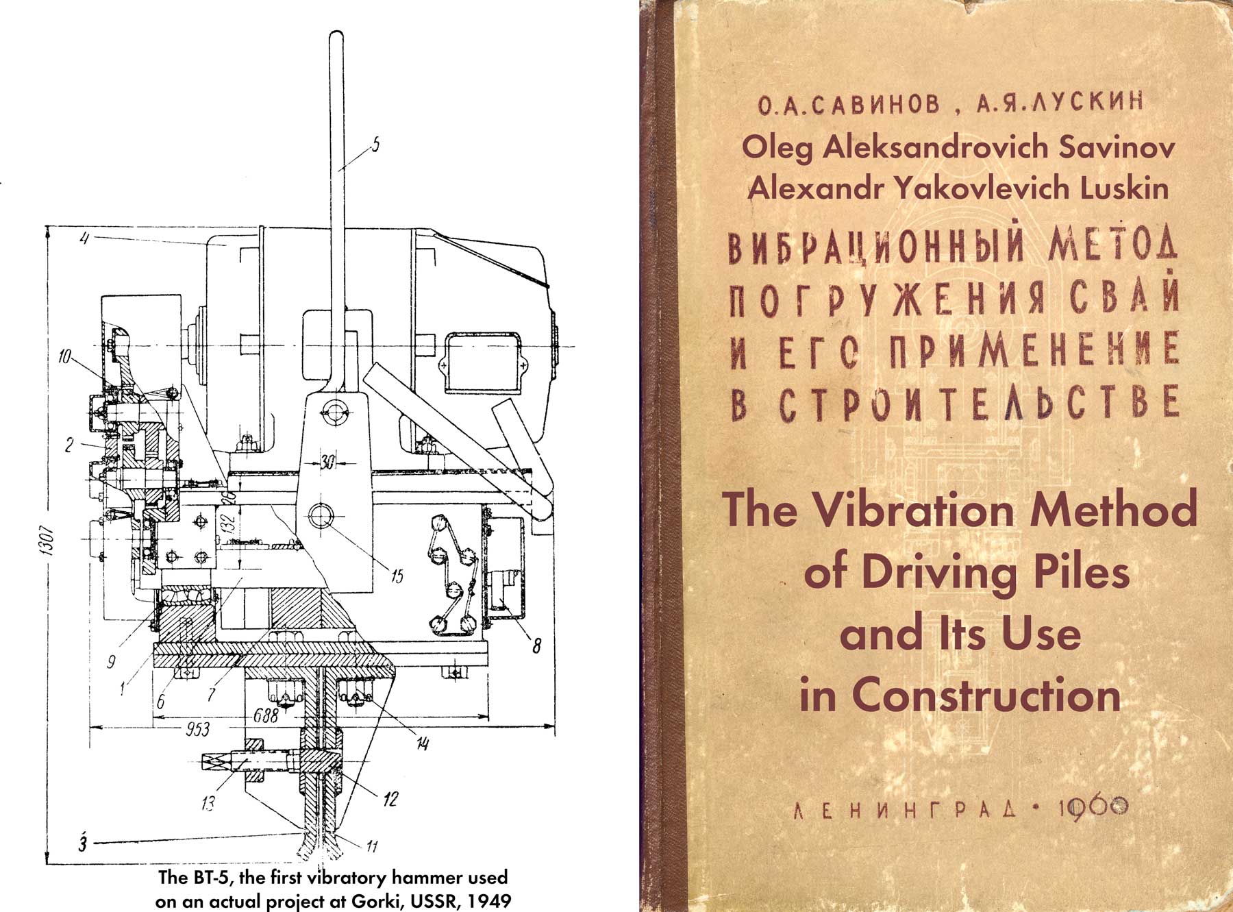
Editor’s Note: this is a topic that has occupied quite a lot of space on this site, starting with Russian Impact-Vibration Pile Driving Equipment and continuing with other pieces. That piece deals some with the early history but is more concerned with the development subsequent to this book at the VNIIstroidormash institute in Moscow. It is interesting to see some of the earlier work by that and other organisations. It is also interesting to note the reliability problems of these machines, something which VNIIstroidormash overcame in part. More recent simulation of these hammers and treatment of the theory can be found at one piece featured at Two Papers on Vibratory and Impact-Vibration Hammers.
According to the principle of the device, impact-vibration hammers can be divided into two types.
The first one, which has received the greatest distribution, includes the so-called vibratory hammers – vibration machines in which the vibrator does not have a rigid connection with the immersed body and, during operation, hits it like a limiter.
The second type includes machines, which include a vibrator rigidly connected to the immersed body, and a hammer driven by a separate mechanism.
The most characteristic diagrams of the device of impact-vibration hammers are shown in Figure 62.

The vibratory hammer designed by I. A. Miroshnichenko*, shown in the first diagram, consists of one vibrator 1, freely installed on pile 2. There is no two-way connection between the vibrator and the pile, and the vibrator is also free from external connections. In practice, it consists of two electric motors built into a common rigid housing. eccentrics and, if necessary, synchronizer gears are attached to the ends of the shafts.
*Author’s Certificate no. 76460 with priority from 12 November 1948.
The movements of the vibrator in the event that the amplitude of the disturbing force exceeds its own weight in magnitude, consist of successive cycles, each of which is a flight, starting with the separation of the vibrator from the pile, the head of which plays the role of a limiter, and ending with a blow to the pile; periods of stagnation may occur between cycles. Under the impact of the vibrator, the pile sinks, and does not oscillate (the rapidly damping free elastic oscillations of the pile arising under the impact of the impacts in this case may not be taken into account.)
As you can see, by the nature of the impact on the submerged body, the impact-vibration plunger of the type under consideration is a high-frequency hammer, i.e., in essence, it is a percussion projectile. The problem of the motion of such a hammer (assuming that the limiter is stationary and the coefficient of velocity recovery upon impact is equal to zero) was considered by S. A. Osmakov [38], D. D. Barkan O. Ya. Shekhter [7] and L. V. Bespalova [10]; the solution of this problem is also easy to obtain from the work of I. I. Blechman [11], who studied the motion of a material point resting on a vibrating surface.
The research results showed that in this system, periodic movements of many types are possible – single-impact movement with a period of 


The type of movement depends on the ratio between the weight Q of the vibrator and the amplitude P0 of the disturbing force. For 


The efficiency of any hammer is primarily determined by the magnitude of the impulse 

Where
– respectively the moment of the vibrator’s eccentrics and the angular velocity of their rotation;
is some function that depends on the relation
.
*In general, the efficiency of any pile hammer must be evaluated by the amount of movement of the pile after the impact. However, in those cases when the pile is motionless at the moment of impact (with a sufficient degree of approximation to reality, this condition is also observed during the operation of the hammer of the type under consideration,) the momentum of the pile after the impact will be equal to the momentum
The
 coefficient versus ratio.
The advantages of the simplest type of impact-vibration hammer are in a simple design and, most importantly, in easy and convenient adjustment, which is mainly ensured by establishing the correct ratio between the weight of the vibrator and the amplitude of the disturbing force. To obtain the most efficient and quite stable mode of operation of the submersible, it is quite enough that the ratio of
The disadvantage of the submersible is the inability to independently manage such an important factor as the weight of the submersible system. In the first scheme, the loader does not have a shock absorber that could serve as a support for loading, while a rigid connection of the latter with a pile or with a vibrator is impractical.
The disadvantages also include the inability to provide normal conditions for the operation of electric motors; the latter have to be built into the vibrator. Naturally, under these conditions, it is difficult to achieve long-term operation of the motors.
The second scheme of the device of the impact-vibration hammer, adopted by S. A. Tsaplin*, differs from the first one in the presence of springs 3 and a head cap 4, rigidly fastened to the pile. The connection of the vibrator and the pile with the help of springs and the cap in one common system with two degrees of freedom significantly complicates the mode of operation of the submersible. If the piler, made according to Scheme I, always works like a hammer, then arranged according to Scheme II, depending on the parameters of the vibrator, the stiffness of the springs, the size of the gap between the vibrator and the head and the resistance of the soil to pile slippage, it can work as a hammer and as a vibrator.
*Author’s Certificate No. 105358 with priority dated November 5, 1949
Let us consider the features of the operation of a vibratory hammer arranged according to Scheme II. Let us imagine that a pile and a impact-vibration hammer connected to it are suspended on a very elastic shock absorber above the immersion point. By changing the size of the gap, in each case it is not difficult to reach a position at which, during the operation of the plunger, impacts will begin between the bodies of the vibrator and the pile (with a cap.) Experience shows that in this case, stable periodic motions of the system with periods 
Let us start the immersion and observe the behavior of the pile. At the first stage of immersion, when there are no lateral resistances, pile vibrations will occur without periods of stagnation. The submersible works as a projectile of pure vibrational action with a peculiar non-linear oscillation mode.
S. A. Osmakov theoretically and A. Ya. Luskin [29] experimentally showed that such oscillations, in terms of the degree of efficiency of overcoming the frontal resistance of the soil to pile driving, all other things being equal, are less beneficial than ordinary harmonic oscillations caused by the action of a vibrator rigidly connected with a pile. The energy here is spent mainly on the creation of internal impulses arising from collisions of parts of the system separated by springs; external impulses transmitted by the lower end of the pile to the ground are relatively insignificant,
For some time and after the appearance of lateral resistances, the pile will retain the oscillatory nature of the movement, however, intervals of stagnation will begin to be detected in this movement. Studies show that the magnitude of the impulse transmitted by the lower end of the pile to the ground increases.
The specified value will approach the maximum value when the pile ceases to oscillate, and its movement, as well as during the operation of the simplest type of loader, passes into the alternation of periods of stagnation and immersion. Obviously, such a situation can take place provided that

Where
– maximum spring reaction ;
– pile weight with cap;
– value of the resultant lateral resistance,
So, we have established that in the process of driving a pile using a second type of pile driver, three stages should be distinguished:
- The first, when the plunger works as a vibrating projectile
- The second – transitional and
- The third, on which the plunger begins to work like a hammer.
The characteristic sections of the recording of vibrations of the vibrator and pile, corresponding to the indicated stages, are shown in Figure 65. In this case, the pile was a steel pipe with a diameter of 152 mm and a length of 9.7 m.
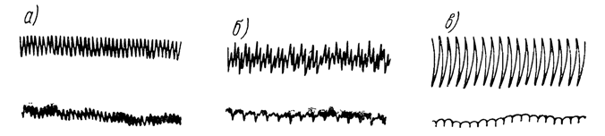
 , 6 – at
  ; c – at
  .
.The study of the third stage, which in most cases determines the duration of the process and the maximum depth of the pile, is of the greatest practical importance. At this stage, with sufficient accuracy for practical purposes, a pile with a cap can be considered as a fixed limiter, which greatly simplifies the task of determining the efficiency of a impact-vibration hammer, finding possible types, and studying the stability of the system’s motion. For the first time in such a formulation, this problem was considered by I. G. Rusakov and A. A. Kharkevich [46], who proceeded from the existence of stable periodic vibrator motions with a period of the perturbing force. S. A. Tsaplin [60] supplemented the solution of I. G. Rusakov and A. A. Kharkevich, showing that stable periodic motions with periods that are multiples of the period of the perturbing force are also possible. In later works of other researchers, the problem under consideration was subjected to further refinement: in particular, L. V. Bespalova [10] found all possible types of vibrator movements and studied their stability.
As a result of these works, it was possible to establish that during the operation of a vibratory hammer built according to Scheme II, in the third stage of immersion, the same types of movements can occur as during the operation of a plunger built according to Scheme I. However, in this case, the type of movement and the boundaries of the area of its existence depend not only on the ratio of the weight of the vibrator to the amplitude of the disturbing force, but also on two other factors – the stiffness of the springs and the size of the gap between the vibrator and the limiter.
S. A. Osmakov, with the participation of O. A. Savinov, studied in detail the issue of the efficiency of a Type II plunger on the assumption that it operates according to the scheme of I. G. Rusakov and A. A. Kharkevich (Figure 66) with an impact velocity recovery coefficient, equal to zero, and the following was established:

- When the plunger operates according to the indicated scheme, to determine the magnitude of the impulse transmitted by the vibrator to the limiter upon impact, the same formula (2.23) can be used, which was proposed for the simplest case when the vibrator freely rests on the limiter and is not connected to it by springs.
The functionbetween the frequency
) of the natural vibrations of the vibrator on the springs (
– mass of the vibrator,
– total coefficient of stiffness of the springs) and the size of the gap
between the vibrator and the limiter.
- The maximum values of
For one-stroke movements, the period of which exceeds, as well as for periodic movements with two or more impacts per period, which have relatively narrow regions of existence, lower values are obtained.
- Considering Table 19, it can be seen that the values of
placed in it exceed the previously obtained value of this coefficient, which corresponds to the simplest Scheme I with the optimal
 | Values of | |
For single-stroke periodic movement (with stagnation and continuous) with a period of  | For single-stroke motion with a period  | |
| 0.2 | 2.1* | 2.1* |
| 0.3 | 2.2* | 2.1** |
| 0.4 | 2.4* | |
| 0.5 | 2.7** | |
| 0.6 | 3.3** | |
| 0.7 | 3.8** | |
| 0.8 | 4.8** | |
| 1.0 | 3.2** | |
(for the scheme of I. G. Rusakov and A. A. Kharkevich)*Values of
However, it should be borne in mind that when driving piles in real conditions, it is difficult to get 
|  |  (in proportion to (in proportion to  |
| 0.3 | 2.2 | 0.46 |
| 0.5 | 2.7 | 0.87 |
| 0.6 | 3.3 | 1.29 |
| 0.7 | 3.8 | 2.14 |
| 0.8 | 4.8 | 3.14-4.36 |
From this it can be seen that the only advantage of Scheme II over the simplest scheme I, which consists in the possibility of increasing the impact force due to the use of a spring connection between the vibrator and the pile, is not significant and in each case can be easily blocked by appropriate selection of the vibrator parameters. At the same time, Scheme II has, in comparison with Scheme I, significant drawbacks, which include:
- low efficiency of the pile driver at the initial stage of pile driving;
- the complexity of adjusting the submersible for the optimal mode of operation;
- great complexity of the design;
- the need for a rigid connection of the cap with the pile, leading to some complication of the process of piling,
The use of Scheme II may be useful only when designing vibratory hammers for driving elements with significant lateral resistance (for example, casing drill pipes,) where due to the use of springs it will be possible to somewhat reduce the weight of the vibratory hammer.
Everything said above regarding Scheme II can be extended to Scheme IIa.* A distinctive feature of this latter scheme is the use of a single-shaft vibrator instead of a two-shaft one; with elastic springs, such a vibrator works in the same way as a directional one, without causing transverse vibrations of the pile, and retains the same advantages and disadvantages as those arranged according to Scheme II.
*Suggested by D. D. Barkan, V. M. Slavsky, F. F. Voskresensky and others.
It would seem that the above comparative characteristics of Schemes I and II, in some cases, prompts preference for the first scheme. Meanwhile, as we will see below, until recently, the efforts of most researchers were aimed at creating submersibles built exactly according to the second scheme. It is necessary to further compare the efficiency of both types of pile drivers in the experiment with a thorough study of the influence of various factors on the pile driving process.
It is especially important to emphasize that Schemes II and IIa, as well as Scheme I, do not include elements that could serve as a support for the weight and, thus, do not provide the ability to independently control the weight of the system. Scheme III, proposed by O. A. Savinov, and Scheme IV, proposed by V. V. Eliseev, are deprived of this serious drawback. In both schemes, spring shock absorbers 6 are provided for attaching load 5; otherwise, the schemes do not differ from Schemes I and II. Thanks to such a device, in each case it is possible to easily change the weight of the system without changing the intensity of the dynamic impact of the vibrator on the pile. In addition, the presence of a sprung load makes it possible to significantly alleviate the operating conditions of the electric motor.
At the same time, in Schemes III and IV, the vibrator mechanism continues to serve as the impact part, which is also a disadvantage. The latter is eliminated in Schemes V and VI. In these schemes, special ram points 7 are provided for striking. In Scheme V, developed by D. D. Barkan [8], the vibratory driver is installed with the help of springs 3 on an ram point 7 connected to the headband by springs 3. In scheme VI, proposed by A. Ya. Luskin,* dummy 7 with the help of springs 3 is mounted on a vibrator, which rests through springs 3 on the headband.
*Author’s Certificate No. 101110 with priority dated February 11, 1954
Scheme V is basically a percussion projectile; the vibrations that the vibrator can communicate to the pile cannot be significant in this case due to the presence of two shock absorbers 3 and 3, separated by a blank 7. On the contrary, the Scheme VI, by giving sufficient rigidity to the spring 3, makes it possible to excite strong vibrations of the pile. Thus, this scheme is easy to use for the device of a vibrating pile driver, in which the blows of the blank are not the main, but an additional type of dynamic impact on the pile.
The main disadvantage of Schemes V and VI is their significant complexity, which makes it extremely difficult to adjust the loaders for the optimal mode of operation,
Other schemes for the device of vibratory hammers are also known. So, for example, a VPP-type vibratory driver, which does not have a rigid connection with a pile, begins to work as a impact-vibration projectile.
Unlike the first type of impact-vibration hammers (vibratory hammers,) the design development and experimental verification of which have received considerable attention in recent years, the second-type impact-vibration hammers still exist only on paper.
So, for example, A. S. Golovachev and V. I. Chernyaev proposed a scheme and design of a vibratory-impact plunger, characterized in that it includes an independently acting directional vibrator rigidly connected to a pile and a hammer, reciprocating motion provided by a separate electric motor. We should also mention the scheme of the vibratory-impact plunger proposed by P. D. Lobasov, A. Ya. Luskin and Yu. G. Mehlbart*, which combines intense rotational vibrations of the submerged element and impact on it.
*Application No. 591099 dated February 1, 1958
Experience in the use of vibratory hammers of the simplest type, built according to Scheme I (Figure 62,) is extremely insufficient. Only a few samples of low-power hammers are known that are successfully used in the Mosgaz and Lengaz trusts for drilling holes with a diameter of 20-25 mm and a depth of 1-1.5 m. Each of these vibratory hammers is an electric motor with a power of about 0.5 kW, having a shaft at the ends rotor two eccentric. A piece of pipe is welded to the motor housing, into which the drilling tool freely enters.
In addition to these special machines, there are known cases of using BT-9 vibratory hammers in drilling operations, operating according to Scheme I without connection to the submerged body. The specified vibrator has the following technical characteristics:
| Eccentric Moment | 200 kg-cm |
| Vibration Frequency | 1250 RPM |
| Motor Power | 5.8 kW |
| Total Weight | 400 kg |
| Dimensions: | |
| In Plan | 700 X 470 mm |
| Height | 1200 mm |
To work according to this scheme, a short steel rod is screwed into the head of the vibratory driver, which freely enters a special bushing screwed onto the drill rods, through which the vibroprobes are immersed into the ground under impact.
Impact-vibration hammers II of the scheme, several samples were developed that differ in their parameters and the design of individual units. These include impact-vibration hammers of the VTs-2, VTs-Z types designed by S. A. Tsaplin, developed at DORNII [60], of the VMTs-3, VMTs-3A types (Table 21,) V-5, S-402 and S -468, developed under the guidance of the same author at VNIIStroidormash, type VM-4 and VM-7, developed under the guidance of A. S. Golovachev at the Central Research Institute of the Ministry of Transport Construction, etc.
| Specifications | Machine Model | |
| VMTs-3 | VMTs-3a | |
| Eccentric Moment, kg-cm | 500 | 650 |
| Rotational Speed of Eccentrics, RPM | 1460 | 1460 |
| Dynamic Force, tons | 12.0 | 15.5 |
| Power of Electric Motors, kW | 18 | 28 |
| Ram Weight, tons | 1.1 | 1.1 |
| Total Weight of Hammer, tons | 1.6 | 2.2 |
| Machine Height, mm | 1190 | 2630 |
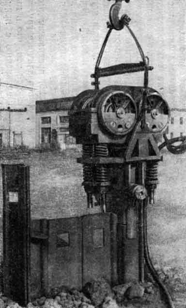
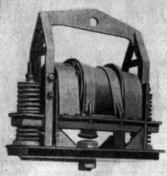
Vibratory hammers of the VTs-2 and VTs-3 types have not received practical application. Vibratory hammers of the VMTs-3 type (Figure 67) were tested at the construction of the Stalingrad hydroelectric power station. During the tests, the employees of the Central Mechanical Repair Plant of the SGES* together with S. A. Tsaplin made changes to the design of the vibratory hammer, as well as improved its main parameters and created a new model VMTs-3A (Figure 68,) which was used to immerse a heavy sheet pile of the type Larsen V up to 13 m long into impervious curtains under the spillway dam.
*V. B. Buslov took part in the modernization of the vibratory hammer, along with A. M. Makarov, I. S. Gusman and others.

Between the shafts of electric motors included in the design of these impact-vibration hammers, there is no mechanical synchronizer. Experience shows that in those cases when the impact mode is set, self-synchronization of the rotation of the shafts with eccentrics occurs.
The parameters of the working springs in vibratory hammers are selected empirically. When setting up the machines for the optimal mode, they worked with the number of strokes, two times less than the number of revolutions of the eccentrics.
Based on the results of the production application of vibratory hammers of the VMTs-3 and VMTs-3A types, VNIIStroidormash developed a new model of the S-467 vibratory hammer, designed to drive metal sheet piles and reinforced concrete piles with a cross section of 35 x 35 cm and a length of 10 -12 m. Two of its electric motors will have total power 56 kW. The weight of the vibratory hammer is approximately 2.5 tons.
Another model of the S-402 impact-vibration hammer (Figure 69,) intended for driving wooden piles with a diameter of 20-22 cm into the ground, has been transferred to serial production. The technical characteristics of the S-402 impact-vibration hammer are as follows:
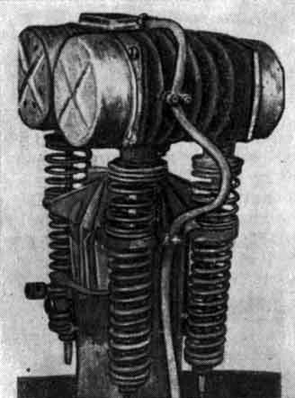
| Greatest Eccentric Moment | 110 kg-cm |
| Rotational Speed of Electric Motors | 1440 RPM |
| Largest Dynamic Force | 3.2 tons |
| Power of Two (2) Electric Motors | 5.6 kW |
| Total Weight of Vibratory Hammer | 320 kg |
| Dimensions: | |
| In plan | 525 x 50 mm |
| Height | 1100 mm |
The S-402 impact-vibration hammer set includes two types of springs that differ in stiffness. With some springs, the number of blows of the vibrator on the cap, when the pile is pinched in the ground, is 720 impacts/min, with other springs – 480 impacts/min.
As shown by the tests of the first samples of this submersible. regardless of the stiffness of the working springs, its operation in the initial period of immersion is not very effective. Pinching of the pile and improvement of the impact-vibration hammer operation mode occurs in many cases only after part of the weight of the pile driver is transferred to the pile, in combination with which the impact-vibration hammer must work. In practice, such additional sprung loading is carried out by a crane winch, the traction force of which is transmitted to the pile through special tension springs by means of a steel rope and a system of blocks.
Vibratory hammers of the VM-4 and VM-7 types (Table 22) are intended for immersing steel sheet piles and pipes in various soils.
| Specifications | Hammer Model | |
| VM-4 | VM-7 | |
| Eccentric Moment, kg-cm | 100 | 312 |
| Rotational Speed of Eccentrics, RPM | 2925 | 1440 |
| Dynamic Force, tons | 9.5 | 7.2 |
| Power of Two (2) Electric Motors, kW | 9 | 14 |
| Ram Weight, kg | 370 | 590 |
| Total Weight of vibratory hammer, kg | 500 | 850 |
| Total stiffness of springs, kg/cm | 500 | 1000 |
Impact-vibration hammers of the VM-4 and VM-7 types are distinguished by the fact that they use the most flexible springs compared to those used in other submersibles of this group. Thus, for a BM-4 vibratory hammer the coefficient 


Vibratory hammers built according to Scheme IIa (single-shaft) include impact-vibration hammers of the VMG type, developed at the Research Institute of Foundations under the direction of D. D. Barkan, M. G. Efremov, V. N. Tupikov, and impact-vibration hammers of the VM type, created at TsNIIS under the guidance of A. s. Golovachev.
Vibratory hammers of the VMG-2 type (Figure 70) and VMG-5 are designed for drilling exploration wells.
The technical characteristics of single-shaft vibratory hammers designed by TsNIIS are given in Table 23.
| Specifications | Hammer Model | ||
| VM-8 | VM-9 | VM-10 | |
| Eccentric Moment, kg-cm | 160 | 512 | 625 |
| Rotational Speed of Eccentrics, RPM | 1440 | 1450 | 1460 |
| Power of the Electric Motor, kW | 7 | 20 | 28 |
| Ram Weight, kg | 350 | 650 | 700 |
| Weight of the Vibratory Hammer, kg | 500 | 800 | 800 |
| Total stiffness of the springs, kg/cm | 500 | 800 | 800 |
For vibratory hammers given in Table 23, the use of relatively flexible springs is also characteristic, giving the values of the coefficient 
The purpose of single-shaft impact-vibration hammers designed by TsNIIS is basically the same as that of two-shaft ones. The design of single-shaft vibratory hammers is simpler. In addition, a device is provided that allows you to change the direction of impact, due to which impact-vibration hammers of the VM-8, VM-9 and VM-10 types can be used to extract sheet piles and pipes from the ground.
The main purpose of vibratory hammers of types VM-9 and VM-10 is to immerse and extract pipes with a diameter of 400-800 mm to form holes in the ground for subsequent vibro-driving of pile foundations under the supports of the contact network of electrified railway lines.
Vibratory hammers operating according to Schemes III and IV do not currently exist.
Scheme V was studied in detail by D. D. Barkan and O. Ya. Shekhter [8]. On the basis of these studies, a laboratory model of such a plunger with a 0.4 kW DC motor with a speed adjustable up to 3000 rpm was developed and manufactured. The moment of eccentrics of the vibrator could be set equal to 4 and 8 kg-m. The weight of the vibrator with the motor was 35 kg, the weight of the ram (blank) was also 35 kg. The stiffness of both the upper set of springs and the lower working set was taken in accordance with the calculation equal to 136 kg/cm.

When testing the model, a pipe with a closed end 50 mm in diameter was immersed in sandy soil to a depth of 4 m, and vibrations of the vibrator and impact mass were recorded. As a result of these tests, it was found that the nature of the obtained vibrograms closely corresponds to the calculated ones. In addition, it was confirmed that in the proposed scheme of the driver, the vibrator is well isolated from the harmful effects of blows inflicted by a blank on the headband.
The sixth scheme was used as the basis for the device of an experimental impact-vibration hammer of small dimensions and a prototype production sample of a pile impact-vibration hammer of the SVM-1-0 type, developed at VNIIGS under the guidance of A. Ya. Luskin.
The design of the experimental vibratory hammer (Figure 71) made it possible to tune it to various operating modes, vibrating – according to the simplest scheme and runway scheme, impact-vibration (scheme II) and vibration-impact (scheme VI.) The SVM-1-0 submersible could only work according to scheme VI.
The technical characteristics of these drivers are given in Table 24.
| Specifications | Machine Type | |
| Experimental Sample | SVM-1-0 | |
| Largest eccentric moment, kg-cm | 80 | 800 |
| Rotational Speed of Motors, RPM | 1420 | 1450 |
| Largest dynamic force, tons | 1.8 | 18.0 |
| Power of Two (2) Electric Motors, kW | 4.4 | 56 (74) |
| Ram Weight, kg | 160 | 1000 |
| Vibrator Weight, kg | 160 | 1250 |
| Total Machine Weight, kg | 390 | 2800 |
| Damping spring rate, kg/cm | 3000-8300 | 18000 |
| Coefficient of stiffness for working springs, kg/cm | 220-1800 | 1800 |
| Dimensions in mm: | ||
| In Plan | 620 x 410 | 1240 x 840 |
| Height | 1200 | 2430 |
The study of various modes of operation of the experimental loader consisted of repeated driving of round tubular piles (with a closed end) with a diameter of 152 mm, a length of up to 9.7 m and an I-beam No. 20 11 m long.
Without dwelling on the description of the entire complex of experimental work, we briefly touch on the main results obtained during their implementation.
Typical graphs of the dependence of the depth of immersion of round piles 6.4 and 9.7 m long on time are shown in Figure 72. Graphs of the dependence of the power consumption on the depth of piles are also given there. As can be seen from the figure, the highest immersion rate was obtained when operating in the vibration-impact mode (according to Scheme VI.) When operating in the impact-vibration mode (according to Scheme II,) the lowest speed was obtained from the three compared modes.

For a diving depth of 7.5 m, the following average velocities were obtained:
- According to Scheme VI: 1.25 m/min
- According to Scheme VPP: 0.75 m/min
- According to Scheme II: 0.30 m/min
In the initial stage of driving, the best results were given by drivers designed according to Schemes VI and VPP. Specially, experience in driving the surface layer of crushed stone has shown that such layers are easily passed using these drivers, but are not available for driving with a loader constructed according to Scheme II. At the same time, in terms of the maximum immersion depth, the best results were obtained when working according to Scheme II (in impact mode.) While when working according to the VPP scheme (with the given parameters of the machine,) it was possible to immerse the pile to a depth of 7.5 m, and according to Scheme VI – to a depth of about 8 m. When operating according to Scheme II, a pile 9.7 m long was immersed to the entire depth without a significant decrease in the steady-state rate of immersion. The impact-vibration mode has another advantage, which consists in the fact that the power consumption was on average two times less than when operating in the VPP mode and 2.5-3 times less than in the VI mode. However, it is easy to see that in terms of power consumption for driving the entire pile to a certain depth, which is the same for all modes, Scheme II is inferior to the other two, since immersion with this scheme takes 2.5 and 4 times more time, respectively.
The results of experimental work are confirmed by the experience of production tests and the use of vibratory hammers and vibratory hammers at Stalingradgidrostroy. In the pit of the spillway dam, it was not possible to drive Larsen V type sheet piles 13 m long to the entire depth with vibratory pile drivers of the VPP-2 type due to the presence of hard layers of pebbles, clays and sandy-silty rocks in the sand thickness. However, in those places where sheet piles did not encounter such obstacles, they sank to the full depth to the underlying sandstones in 2-3 minutes. In all other places, the sheet pile was sunk to a depth of 5-8 m with vibratory hammers of the VPP-2 type, and then it was achieved with air/steam hammers of the S-231 type.
The VMTs-3A impact-vibration hammers tuned to the optimal mode in all cases immersed sheet piles to the full depth, punching through dense layers, including sandy-silty rocks. The pile sinking speed has always been relatively small, regardless of the density of the soil layers passed by the pile.
About 500 tons of sheet piles were driven by sixteen vibratory hammers.
It should be noted that the durability of vibratory hammers turned out to be completely insufficient. Even after the design flaws that reduced their mechanical strength were eliminated, one vibratory hammer managed to load 10-12 sheet piles, after which it failed, most often due to the rotor of the electric motor touching the stator.
It is interesting to compare the technical and economic indicators of the use of these vibratory hammers and vibratory drivers. Such an analysis was carried out by the authors on the basis of field observations, the results of which basically coincide with the data (Table 25,) which are given in his brochure by V. E. Chubov [64].
| Parameters | Machine Type | ||
| Air/steam hammer S-231 | VMTs-3A | VPP-2 | |
| Average productivity per net work each hour per ton | 0.3 | 3.5 | 12.4 |
| Average productivity per shift, m | 1.1 | 5.3 | 7.0 |
| Average labor output per metre per person/hour | 28.8 | 7.6 | 6.9 |
| Average duration of one cycle in minutes | 56.0 | 41.0 | 22.6 |
| Average immersion speed in m/min | – | 0.5 | 2.6 |
| Power consumed by the unit, kW | 160 | 18-21 | 60-135 |
| Specific power consumption per 10 m immersion, kWh: | |||
| a) all with a crane | 875 | 30.0 | 31.5 |
| b) without a crane | 570 | 6.0 | 11.4 |
There are some discrepancies between the results of field observations of the authors and the data in Table. 25. Thus, according to the measurements made by A. Ya. Luskin and Yu. M. Grigoryan, the power consumed by the VmTs-3A vibratory hammer varies within vibration, within 60 – 80 kW. Given in Table. 25 The upper power limit of 136 kW seems to refer to the experimental data when the machine was tested. having high moments of imbalances and vibration frequency,
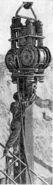
In 1955, two prototypes of a vibratory hammer of the SVM-1-0 type were tested at Stalingradgidrostroy (Figure 73.) In one of them, built-in electric motors were used, each with a power of 28 kW, in the second – with a power of 37 kW.
As a result of the tests, it was found that during the operation of the vibratory hammer, intense vibrations of the pile being immersed and, at the same time, strong impacts of the ram point (drummer) on the head occur, providing a high immersion capacity of the machine. However, it turned out that the submersible consumes a large amount of electricity. It was found by measurements that the electric motors consumed from 70 kW in the initial stage of immersion to 144 kW when driving a sheet pile into sandy-silty rocks. The reason for such a significant energy consumption lies in the fact that, firstly, a significant part of it is spent on moving the pile into the ground with a greater amplitude than in purely vibrational mode, and secondly, in the impact of the ram point with the headpiece.
The amount of energy consumed in this driver can be reduced by changing the parameters of the vibrator and the stiffness coefficient of the working and damping springs. However, in this case, the vibrations of the pile will significantly decrease, therefore, the principle of operation will change, approaching the principle underlying Scheme V. It can be seen from the foregoing that not one of the currently existing impact-vibration hammers has advantages over vibratory drivers.
Considering that vibratory hammers built according to some of the considered schemes have a high loading capacity and low energy consumption, further work should be intensified to improve their design, as well as to create new types of impact-vibration drivers and sheet piles. In particular, of great practical interest is the creation of such hammers, which would combine the positive qualities of vibratory hammers (high sinking speeds, high productivity) and vibratory hammers (large loading capacity and relatively low power.)
Such a loader, for example, could be a machine that, in non-cohesive and weak clay soils, would operate in a vibration mode, and when meeting with dense layers of soil, it would automatically or by simple switching be transferred to a impact-vibration mode of operation.


3 thoughts on “Impact-Vibration Hammers”