
For the rest of the book, click here.
The main distinguishing feature of the simplest type of vibrodriver (Figure 27) is that all its parts are connected to each other and to the submerged body into one common whole. The vibrator consists of an electric motor 1, a directional vibrator 2 and a head 3; the design may also include loading plates 4. The advantage of the simplest type of vibrators is the simplicity of the design.
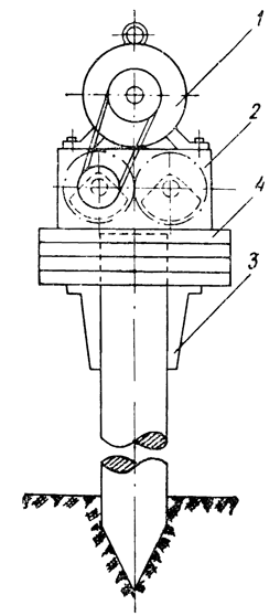
However, these machines also have disadvantages. The first and most significant is the impossibility for this device of the machine to control separately two of the three main factors affecting the pile driving process – the amplitude of vibrations and the magnitude of the immersing pressure. This circumstance finds its expression in a contradiction between the requirements for the weight of the submerged system and the vibration regime: to increase the depth and speed of immersion, it is necessary to increase the weight of the vibratory driver to certain limits, which, when all parts of the system are rigidly fastened together, it leads to a decrease in the amplitude of vibrations and thereby to deteriorating diving conditions.
It is not difficult to verify the validity of what has been said. Recall that an indispensable condition for successful immersion is the complete removal of the pile from the ground, at which the amplitude of its vibrations can be determined from the approximate expression:

Where
- K – the moment of eccentrics of the vibrator;
- Q is the total weight of the pile, vibrator and load; .
- ξ – coefficient taken equal to 0.8-1.0.
Considering this expression, one can see that the amplitude of vibrations is inversely proportional to the weight of the system, therefore, any increase in the value of Q will result in a decrease in the value of A, which confirms the correctness of the above statement.
The second disadvantage of the simplest type of vibratory hammers is the difficult operating conditions of the electric motor, which, being installed on the vibrator, experiences the same intense vibrations during the operation as the pile being driven. This disadvantage affects stronger and higher frequencies of vibration. Indeed, as the data of experimental studies presented in the first chapter show, the process of vibrational immersion can occur successfully at different frequencies, but at approximately the same vibration speed (equal to the product of amplitude and frequency,) which is about 50-80 cm/sec. This means that at a frequency of about 500 RPM, the acceleration of machine vibrations (on which the durability of the electric motor design mainly depends) will be 2.5-3.5 g, at a frequency of 1500 RPM – 7.5 -10 g and at 3000 RPM – 15 – 20 g. In the first case, almost any electric motors can work without damage for a long time, in the second case, only the most durable of them with a relatively low power (up to 10-15 kW,) and in the third case, it is almost impossible to ensure sufficiently durable operation of electric motors of existing types.
Finally, the third drawback of vibratory hammers of the type under consideration is associated with the impossibility of transmitting to them external forces directed along the line of action of the vibrator during its operation without the help of a special shock absorber. This shortcoming makes, first of all, the use of these machines in such works as, for example, the extraction of metal sheet piles, difficult. During the performance of such works, the direct suspension of the vibrating machine to the hook of the load-lifting crane is unacceptable for safety reasons. The introduction of a special shock absorber requires an increase in the lifting height of the hook and, most importantly, significantly complicates the operations of lowering and laying the extracted sheet pile; the last circumstance ultimately leads to a decrease in productivity. Secondly, the inability to transfer external forces directly to the vibrator along the line of action of the vibrator does not allow driving piles without guides, which limits the possibility of using jib cranes in these works; meanwhile, in many cases it is the use of the latter (without guides) that makes it possible to achieve the highest labor productivity.
All these shortcomings limit the scope of application of the simplest vibratory drivers to those cases where the required vibration frequency is relatively low (no more than 600-800 RPM,) and according to technological conditions, the use of guide devices is acceptable and does not cause a significant decrease in labor productivity or increase in the cost of work. Due to the simplicity of the design, the use of vibratory drivers of the simplest type in this area is quite justified.
Vibrodrivers of the simplest type, according to their purpose and parameters, can be classified into three main groups:
- for immersion of metal sheet pile and steel pipes;
- for driving reinforced concrete piles;
- for driving heavy iron-bearing piles/shells of large diameter.
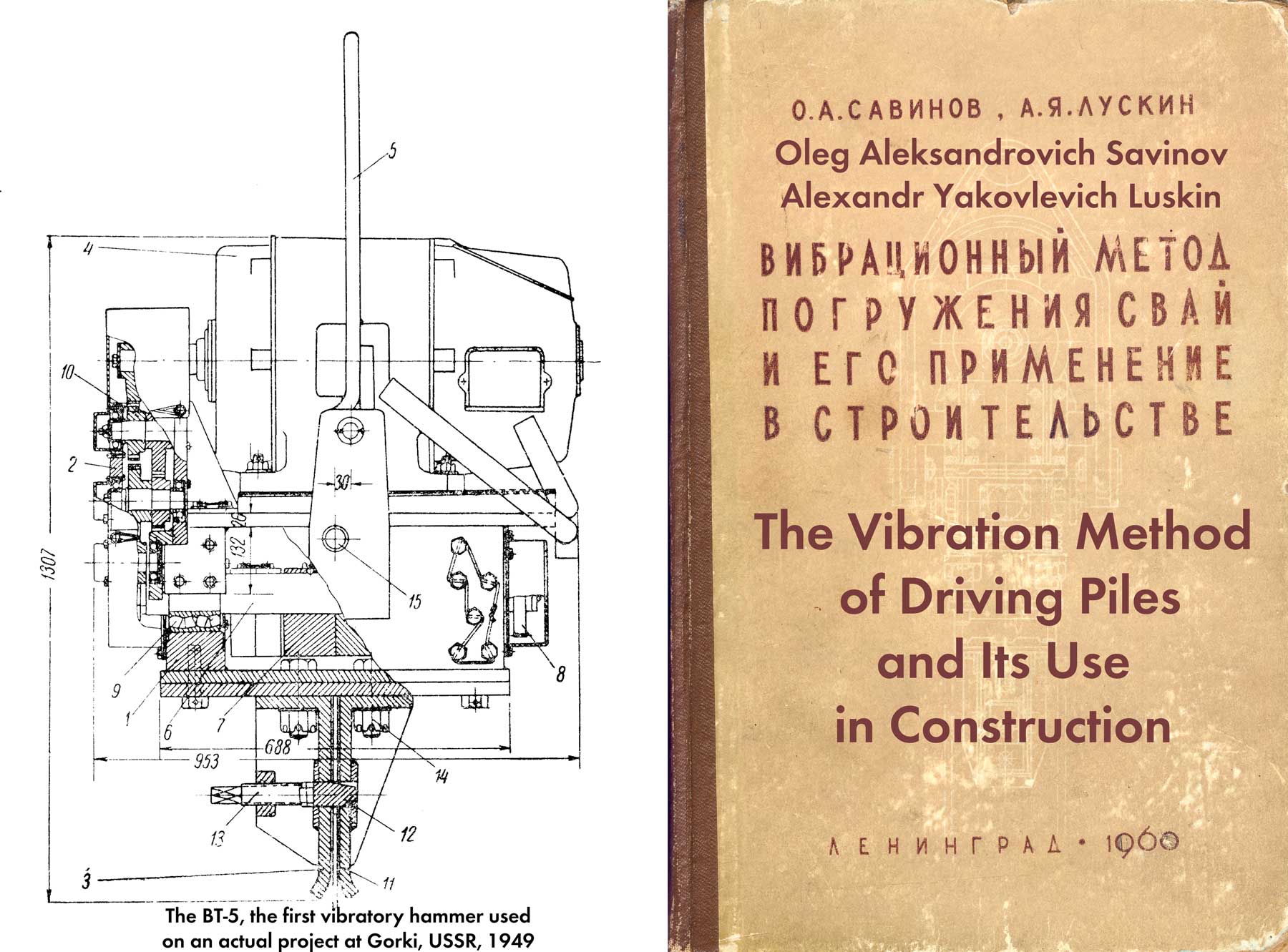
The first group includes relatively light vibratory hammers of the V-100 series, developed under the guidance of Professor D. D. Barkan at the Research Institute of Foundations; here we will include the first production model of a vibratory driver designed by D. D. Barkan and V. P. Tupikov of the BT-5 type; to the second – low-frequency vibratory drivers of the VP type designed by B. P. Tatarnikov, developed at the Research Institute of Bridges; to the third – powerful longitudinal vibratory hammers of the VP and NVP type, designed by B.P. Tatarnikov and VPU, developed in the Wuhan Bridge Construction Administration in the PRC by a creative community by Soviet and Chinese specialists.
All vibrodrivers of the first group are of the same type in their design, exactly correspond to the circuit diagram (Figure 27) and, with the exception of the BT-5 vibrodriver, have approximately the same parameters. The technical characteristics of vibratory drivers of the first group are given in Table 11.
| Parameters | BT-5 | B-102 | B-104 | B-108 |
| Eccentric Moment, kg-cm | 350 | 4000 | 3140 | 3000 |
| Rotational Speed, RPM | 2350 | 700 | 700 | 800 |
| Dynamic Force, tons | 21.8 | 21.8 | 17.0 | 21.2 |
| Vibrator Weight, tons | 1.3 | 1.8 | 2.0 | 1.6 |
| Free-Hanging Amplitude of Vibrator Without a Pile, mm | 2.7 | 22.2 | 15.7 | 18.7 |
| Electric Motor Power, kW | 28 | 28 | 28 | 28 |
| Overall Dimensions in Plan, mm | 950 x 910 | 1170 x 880 | 910 x 680 | 958 x 924 |
| Height, mm | 1310 | 1390 | 1750 | 1470 |
Vibratory hammer type BT-5 (Figure 28) for immersing a metal sheet pile of light profiles (type ShP and ShK) into homogeneous water-saturated loose and medium-density sandy soils to a depth of 8-10 m consists of a vibrator 1, a gear reducer 2, a head cap Z, electric motor 4 and suspension 5. It is a welded box with two shafts b and eccentrics 7. Synchronization of the rotation of these shafts is carried out by two gears 8 located outside the vibrator housing under a special casing. The supports for each shaft are four spherical roller bearings 9 (two on each support,) pressed into the walls of the housing. The reducer transmits rotation from the electric motor to shafts with eccentrics.
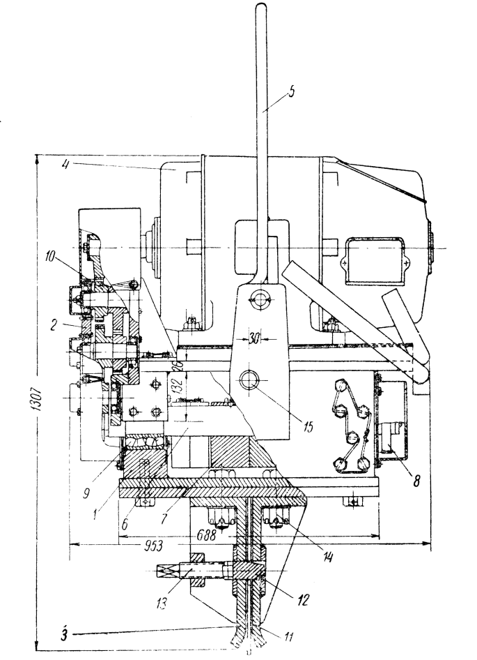
For the first time, a wedge head was used on a vibratory driver for rigid fastening of a vibrator with a submerged sheet pile, the principle of which turned out to be very successful. It consists of two cheeks 11, a wedge 12 and a screw 13. The cap is fastened to the bottom of the vibrator box using bolts 14.
A distinctive feature of the first sample of the sheet pile vibratory driver was the presence of special trunnions 15, located approximately at the level of the center of gravity of the entire machine, but with some offset from the vertical axis. The trunnions supported the vibratory driver on the charging stand and, rotating on the trunnions, turned to a horizontal position for connection with the sheet pile.
The disadvantages of the BT-5 type vibrodriver are the unsuccessful selection of parameters at which the vibration amplitude is too low, and insufficient durability.
Currently used other designs of vibratory hammers of this group according to the device scheme are similar to BT-5, but differ from it in parameters, purpose and design.
Vibratory hammer type B-102 is intended mainly for immersion to a depth of 8-10 m in weak water-saturated soils of the inventory pipe used for the installation of bored sand pile-drains. The machine is built on a two-shaft scheme. On the shafts placed in a welded housing, there are eccentrics; some of them are fixed, while others can be rotated and fixed at angles at which their static moment is 1000; 2000; 3000 and 4000 kg-cm.
The transmission of rotation from the electric motor to the vibrator shafts is carried out by V-belts, the tension of which is regulated by a special roller.
The caisson pipe is tightly attached to the vibrator. To extract it from the ground after filling, the vibrator has a spring shock absorber that isolates the crane boom or pile driver from vibrations. For connection with the guide post of the pile boom, there are special brackets on the vibrator body that slide freely along the post during vertical movements of the vibrator.
The V-104 type vibratory driver is designed to drive metal sheet piles of all profiles to a depth of 12-14 m. With a special shock absorber, this vibratory driver can also be used to extract sheet piles from the ground, as well as to install bored piles.
In contrast to the designs discussed above, the V-104 vibratory driver has a split body connected by six long bolts. Such a device greatly facilitates the assembly of the machine. At the same time, the bolted connection under the influence of perturbing forces is upset. The design of the V-belt drive is also unsuccessful. Short belts in the presence of a pressure roller quickly fail. The axles of the suspension hinges are located much higher than the line passing through the center of gravity of the machine. Therefore, it is practically impossible to transfer the vibratory driver hanging on the hook of the crane to a horizontal position, which complicates the operation of fastening the sheet pile with the vibrator.
The designers used a wedge with a pulling screw in the headband. The lower face of the wedge is inclined, and its axis is parallel to the horizontal face. Such a device is not rational, since when tightening the wedge, moving along the inclined face, it must also rise upwards, while the friction forces arising under the nut prevent such movement and, therefore, significantly reduce the force with which the wedge presses the sheet pile against the plate headband.
The most advanced is the design of the V-108 vibratory driver, developed in 1955-1956, taking into account the operating experience of V-104 and VPP-2 vibratory hammers. This design uses a chain drive. The gear synchronizer is placed inside the vibrator body. There is also an oil bath for lubrication. Suspension joints are placed close to the axis passing through the center of gravity of the entire machine, etc.
The headband is better designed. Thanks to the pushing screw, the axis of which is parallel to the leading edge of the wedge, there is no displacement of the screw and the wedge relative to each other, which ensures good operation of this device.
Vibratory drivers of the second group are used for driving relatively heavy elements into the ground – solid and hollow reinforced concrete piles. Their technical characteristics are given in Table 12.
| Specification | VP-2 | VP-1 | VP-3 |
| Eccentric Moment, Single Frequency Mode, kg-cm | 4000 | 9300 | 23,600 |
| Eccentric Moment, Dual Frequency Mode, kg-cm | 2500 | – | 14,700 |
| Vibration Frequency, Single Frequency Mode, RPM | 455 | 420 | 408 |
| Vibration Frequency, Dual Frequency Mode, RPM* | 455/910 | – | 408/960 |
| Maximum Dynamic Force, Single Frequency Mode, tons | 8.4 | 18.5 | 44.2 |
| Maximum Dynamic Force, Dual Frequency Mode, tons | 4.2/8.4 | – | 22.1/44.2 |
| Vibrator Weight, tons | 2.0 | 4.5 | 8.0 |
| Vibrator Amplitude, Single Frequency Mode, mm | 20.0 | 20.6 | 32.8 |
| Vibrator Amplitude, Dual Frequency Mode, mm | 12.5 | – | 20.5 |
| Motor Power, kW | 22 | 60 | 100 |
| Overall Dimensions in Plan, mm | 950 x 950 | 1300 x 1240 | 1560 x 1540 |
| Total Height, mm | 1690 | 2100 | 2500 |
*The numerator shows the number of revolutions of the upper shafts with eccentrics, and the denominator shows the number of revolutions of the lower shafts.
The design of VP-l, VP-2 and VP-3 vibratory hammers is of the same type. A distinctive feature of the VP-2 and VP-3 vibratory drivers is the ability to adjust to a two-frequency mode of operation [17]; however, this mode is usually not used, since it does not provide significant advantages over single-frequency ones.
From the schematic diagram of the device of the low-frequency vibratory driver of the VP-1 type, which served as the basis for the design of other machines of this group (Figure 29,) it can be seen that the eccentrics 1 are placed in the vibrator on four shafts 2, to which the rotation from the electric motor 3 is transmitted through gears 4. Synchronization the rotation of all four shafts with eccentrics is provided by four identical gears 5.

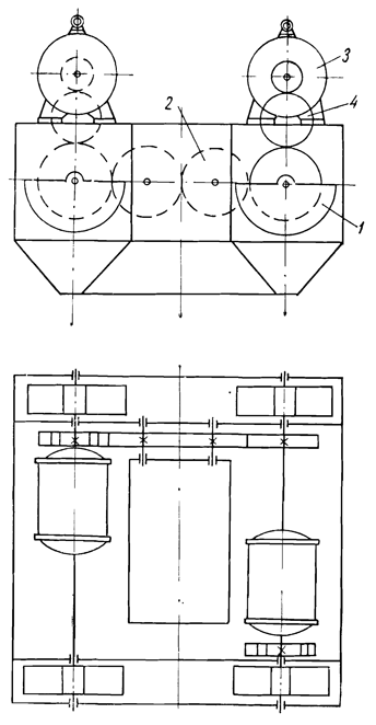
The two-frequency vibrator designed by B.P. Tatarnikov (Figure 30) differs from the single-frequency one in that eccentrics 1 of less weight are fixed on the two lower shafts than the eccentrics 2 of the upper shafts, and the lower shafts are given a different, as a rule, larger one using auxiliary gears 3 rotational speed than the upper shafts.

The VP-1 vibratory loader (Figure 31) consists of three main parts: an electric motor, a vibrator and a head – a device for rigid fastening with a loaded pile.

The electric motor 1 is rigidly fastened to the vibrator body with bolts. In the welded housing 2 on four shafts 3, supported by eight double-row self-aligning spherical roller bearings 4, eccentrics 7 are fixed with clamps 8, bolts 9 and keys 12.
In the first sample of the VP-1 vibratory driver, the eccentrics are dispersed on the shafts. In subsequent samples and other modifications, eccentrics are installed in packages (Figure 31.)
To the bottom plate of the body of the vibrator is attached to the cone cup 5 of the cap. The transmission of torque and synchronization of the rotation of the eccentric shafts is carried out by gears 6. On the outer walls of the vibrator there are four guide rollers 10, with which the vibratory driver is held in the booms of the pile driver or crane, and four frames 11 for attaching the suspension from the cables.
The general view of the VP-3 vibrodriver is shown in Figure 32.

Crane electric motors of the MT type with a phase rotor are installed on the vibratory drivers of the group under consideration. It is practically impossible to use short-circuited electric motors, since the flywheel moment of the eccentric masses of these machines is large and they can only be started smoothly.
Vibratory drivers of the third group are designed for driving thin-walled shell piles of large diameter. A great deal of work on the creation of these powerful machines was carried out by Chinese and Soviet specialists who took part in the construction of the Wuhan bridge [54].
The third group includes vibratory hammers of types NVP-5b, VP-4, VP-5, VP-b, VPU-A and VPU-B. By design and parameters, they are divided into subgroups that differ significantly from each other. The first includes two machines: NVP-56 and VP-6, the technical characteristics of which are given in Table. 13.
| Specification | NVP-56 | VP-6 |
| Eccentric Moment, kg-cm | 50,000 | 113,000 |
| Vibration Frequency, RPM | 293 | 255 |
| Dynamic Force, tons | 48.4 | 82.0 |
| Vibratory Amplitude Without Pile, mm | 43.4 | 71.0 |
| Power of Two Electric Motors, kW | 160 | 220 |
| Plan Dimensions, mm | 2500 x 2080 | 3300 x 3000 |
| Height, mm | 1690 | 2300 |
The NVP-56 vibratory hammer was designed by B.P. Tatarnikov [58] at the Leningrad Institute of Railway Transport Engineers. The design of the VP-6 was developed with the participation of B. P. Tatarnikov in the Wuhan Bridge Construction Administration. These machines, in comparison with other designs, have large moments, eccentrics and a very low frequency (250-300 RPM.) With such parameters, the perturbing forces turn out to be relatively insignificant. According to A.D. Prokhorov, the VP-6 vibratory driver showed poor immersion capacity when immersing a large-diameter shell. Therefore, in all other vibratory pile drivers developed in China, the vibration frequency was assumed to be higher than in vibratory drivers VP-6 and NVP-56.
In terms of design, vibratory hammers NVP-56 and VP-6 are significantly different from other machines of a similar purpose. In the NVP-56 vibratory driver (Figure 33,) there are only four eccentrics 1, placed on two parallel shafts. Each eccentric is a half circle with a diameter of 1200 mm and a thickness of 160 mm. The weight of one such eccentric is approximately 500 kg, and its eccentricity is about 25 cm. Gears 2 serve as a synchronizer for the rotation of shafts with eccentrics. The Machine is driven by two electric motors 3 using gear wheels 4.
A characteristic feature of the design of the vibratory driver is the presence in its body of an opening with a plan size of 800 x 1100 mm, through which it is possible to excavate soil from the shell cavity without removing the vibratory driver.
The VP-6 type vibrodriver has a similar device. It has the same number of eccentrics, the weight of each is about 800 kg, and the eccentricity is about 35 cm.
Electric motors with a phase rotor of the AM-6 type are installed on the vibrators.
The remaining vibratory drivers of the third group (Table 14) VP-4, VP-5 and VPU-A are dual-frequency and do not differ significantly from the machines of the VP type discussed above. Vibratory driver VP-4 is built according to the six-shaft scheme, and VP-5 and VPU-A – according to the eight-shaft scheme. An important feature of the VPU-A type vibrodriver is the ability to change the vibration frequency in the range from 400 to 500 RPM by replacing the drive gears. The design also ensures the synchronous operation of two paired vibratory drivers (Figure 34) mounted on one shell and fastened to it by means of a head adapter. Synchronization is carried out with the help of a gear engaged in engagement with the gears of the drives of both steamed vibrators.
| Specification | VP-4 | VP-5 | VPU-A | VPU-B |
| Eccentric Moment, kg-cm | 37,000 | 38,000 | 35,200 | 30,000-54,000 |
| Vibration Frequency in Single Frequency Mode, RPM | 450 | 500 | 400 450 505 | 500 600 700 800 |
| Vibration Frequency in Dual Frequency Mode, RPM | 450/900 | 500/1000 | 400/800 450/900 505/1010 | – |
| Dynamic Force, Single Frequency Mode, tons | 90 | 120 | 100 130 160 | 150 216 294 384 |
| Dynamic Force, Dual Frequency Mode, tons | 45.0/90.0 | 60.0/120.0 | 50/100 65/130 80/160 | – |
| Weight of the Vibrator, tons | 12.35 | 11.30 | 13.34 | 12.50 |
| Amplitude of the Vibrator without a Pile, mm | 30.0 | 30.8 | 26.2 | 43.2 |
| Motor Power, kW | 155 | 220 | 155 | 310 (Two electric motors with a capacity of 155 kW each.) |
| Plan Dimensions | 1800 x 1650 | 2010 x 1550 | 1630 x 1200 | 1585 x 2100 |
| Height in mm | 3840 | 3620 | 3100 | 1600 |

The VPU-B type vibratory pile driver differs significantly from other machines in its design. Its oscillation frequency can be quickly changed by switching gears in the drive of the machine in steps from 500 to 800 RPM. The general, eccentric moment smoothly varies from 30,000 to 54,000 kg-cm due to the use of the original device.
The housing has only two shafts supported by spherical roller bearings. Each of the six eccentrics is placed on the shafts so that it is between two bearings. The rotation of both shafts, as in all directional vibrators, is synchronized by gears. The shafts are also connected to the electric motor by a gear system.
Each eccentric consists of two parts – fixed, tightly fixed on the shaft, and movable, moving relative to the first in the radial direction. The fixed part has two cylinders, and the movable part has two pistons that fit into these cylinders. In the latter, oil under high pressure can be supplied through the longitudinal and transverse channels in the shafts, by the action of which the moving parts of the eccentrics approach the shaft. Thus, the eccentricity of the eccentric is reduced, and consequently, the total static moment. The weight of all eccentrics in the machine is 2540 kg, their eccentricity can vary from 11.8 to 21.2 cm.
Let us dwell on the features of the two-frequency oscillation mode, the possibility of which is provided in the design of a number of vibratory pile drivers.
During the operation of a two-frequency vibratory driver (see Figure 32,) a perturbing force develops) changing in time according to the law:

Where


Vibratory drivers of the VP type are designed so that in the two-frequency mode, the amplitudes of the disturbing forces of the upper and lower eccentrics are equal to each other, i.e.

In addition, the angular speed of rotation of the lower shafts with eccentrics in these machines is twice the speed of rotation of the upper ones:

The design of the vibrators allows setting the upper and lower eccentrics at some initial moment or in one phase 

According to the authors of the design of dual-frequency vibratory drivers, the first condition, under which the largest value of the disturbing force 
These considerations cannot be regarded as sufficiently convincing. Other things being equal, the use of a two-frequency mode leads to a decrease in the amplitude of oscillations of the pile being driven, which worsens the conditions of immersion; the latter circumstance is confirmed by experimental data. So, N.P. Andreev and N.M. Kolokolov [21] report one case when a VP-2 type vibratory driver, tuned to a two-frequency oscillation mode, plunged a pile with a cross section of 25 x 25 cm, 6 m long into the sandy soil to a depth of 2 .9 M in 12 minutes, after which further immersion practically ceased. In the first 4 min. the pile plunged 2.4 m, but over the next 8 minutes, the driver managed to immerse it only by 0.5 m. In the last 4 minutes. immersion, the oscillation amplitude remained unchanged and equaled 3 mm.
After the vibrodriver was switched to the single-frequency mode and fixed on the same pile, when it was put into operation, the pile began to plunge intensively in 7 min. the pile was sunk another 2.6 m, and the oscillation amplitude at the end of the plunge was 5 mm.
Thus, the dual-frequency mode of operation of VP-type vibrators cannot be recommended for industrial use.
The vibrators that create a disturbing force that varies according to a complex law, with a maximum directed downward or upward, also include a vibrator proposed by P. P. Danilov. * This machine uses elliptical gears, due to which the main shafts, on which the weights are fixed, rotate at a non-uniform angular velocity.
*P. P. Danilov, Author’s certificate 94343 with priority dated December 16, 1950
Such an uneven change in the magnitude of the disturbing force, apparently, does not provide significant advantages, as a result of which vibrators of this type will be no more efficient than conventional vibratory drivers.


3 thoughts on “Vibrators of the Simplest Type”