
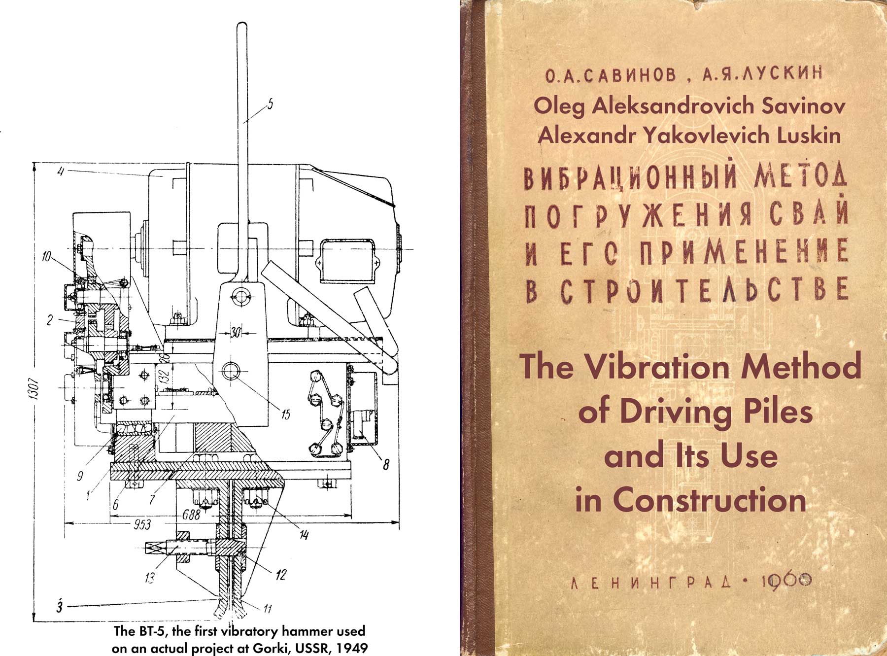
For the rest of the book, click here.
The significant complexity of the phenomenon of vibrational immersion of bodies into the ground and the difficulties associated in choosing the optimal parameters of pile vibratory drivers prompted many researchers to attempt to construct a theory of vibrational immersion and vibroextraction.
Work on the creation of such a theory was carried out in two directions. The first of them includes the works of D. D. Barkan [5], who, investigating the effect of vibrations on internal friction in sands, found that soil particles acquire mobility under this influence and the soil becomes similar to a viscous medium. D. D. Barkan proposed to characterize the mechanical properties of this medium by some coefficient of vibroviscosity, which depends on the physical and mechanical properties of the soil and on the acceleration of vibrations. The results of this study allowed D. D. Barkan to reduce the very complex issue of vibrational pile driving to the problem of immersing bodies in a viscous medium with a variable viscosity coefficient. Having considered this problem, D. D. Barkan obtained formulas for determining the soil resistance to the penetration of bodies, the average sinking speed, etc.
Yu. I. Neimark [37] and almost simultaneously with him I. I. Blekhman [11], M. Ya. Kushul and A.V. Shlyakhtin [26]. vibration penetration is possible without involving the hypothesis of liquefaction or any general change in the physical and mechanical properties of the soil under the influence of vibrations. Based on the usual ideas about the resistance of the soil environment to the penetration of a pile into it, the authors of these works assume that there is a so-called dry friction between the surface of the latter and the soil, and the relationship between the pressure of the lower end of the pile on the soil and its settlement is determined by one or another graph. With this formulation of the problem, it turned out to be possible to obtain formulas for calculating the maximum depth, average speed and time of immersion (or extraction) of the pile.
Without dwelling on the later studies of S. A. Osmakov [38], A. S. Golovachev [22], O. Ya. Shekhter [66] and others, which are very similar in formulation to the works of Yu. I. Neimark, we note that none of the existing theoretical works gives a complete solution of the problem under consideration.
Although the work of D. D. Barkan takes into account the phenomenon of change in the physical and mechanical properties of the soil under certain conditions under the influence of vibrations, which undoubtedly takes place, this account is of an approximate nature, as a result of which the theory constructed by D. D. Barkan does not explain some important experimental facts, for example limited depth of pile immersion for given vibrator parameters, absence of immersion effect at small amplitudes, etc.
Since the works of Yu. I. Neimark and other authors of the second group do not take into account the phenomenon of changes in the physical and mechanical properties of the soil under the influence of vibrations, the solutions they obtained suffer from a certain limitation, since under certain soil conditions, for example, in water-saturated sandy soils, the change in properties is not taken into account soil during vibration immersion cannot but lead to significant errors. At the same time, the theory of Yu. I. Neimark, I.I. Blekhman and M. Ya. Kushul provides a satisfactory explanation for the main experimental facts, which we have considered in detail in the first two paragraphs. This theory generally correctly reveals the mechanical essence of the process of vibrational immersion, which is its main value.
In view of the foregoing, we shall confine ourselves to describing the most significant results of theoretical work in the second direction.
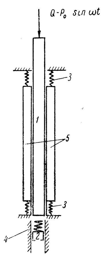
Let us start with the consideration of the calculation models of the driven pile adopted in these works (Figure 20.) The first of these models – Yu. I. Neimark called it the simplest, I. I. Blekhman – “purely plastic”, but for brevity we will call it model No. 1, is built on the following assumptions:
- the pile is an absolutely solid body;
- the soil surrounding the pile is motionless;
- between the side surfaces of the pile and the soil there is only dry friction, the value of which (T) does not depend on the speed of the pile;
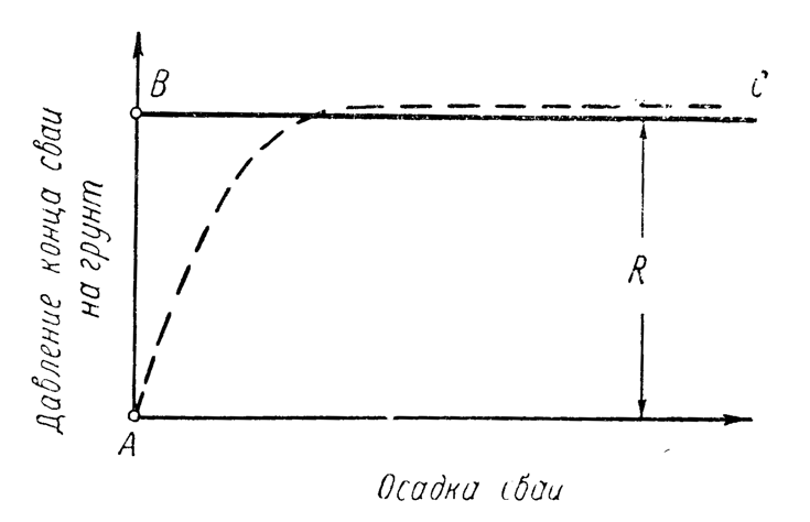
- the relationship between the toe resistance of the soil to the movement of the pile and its settlement is given in the form of a broken line ABC, shown in the graph (Figure 21), and it is assumed that the force R of this resistance does not depend on the speed of the pile; and
- regardless of the nature of the pile movement, the vibrator acts on it with a sinusoidal force
.


Thus, pile 1 (Figure 20) is affected by the force of gravity Q and the sinusoidal force of the vibrator
Model No. 2 is different from model No. 1 by the presence of elastic links 3 and 4, simulating the elasticity of the soil. Links 3 connect the pile with weightless skids 5, links 4 protect the plug 2 from direct impacts of the pile; the interaction between the skids and the plug, on the one hand, and the walls of the model, on the other, obeys the same laws that were adopted in the construction of model No. 1.
When the pile is displaced, the sliders 5 will remain motionless until the elastic forces of the springs 3 reach the value of the friction force T, after which they will begin to slide along the walls of the model; with a reverse displacement, the runners will stop moving again as soon as the elastic forces of the springs become less than the value T. When the end of the pile is pressed to the bottom of the well, the plug spring 4 is first compressed and only after its compression force reaches the value R, the plug itself will begin to move.
From the description of model No. 2 shows that it does not take into account the influence of the inertia of the soil. However, this influence must be very significant. To understand this, it is enough to imagine a pile and an immense soil mass into which it plunges, and take into account that the mass is composed of a material with a volumetric weight approximately equal to the average volumetric weight of the pile material (for reinforced concrete piles) or even exceeds it (wooden and tubular piles, hollow steel and reinforced concrete piles.) Although indirect, Experience provides very convincing proof of the validity of the stated position. For example, as a result of natural measurements made by D. D. Barkan [5], F. A. Kirillov and S. V. Puchkov [24] found that the natural oscillation period of a pile is almost independent of the depth of its immersion. Taking into account that the stiffness coefficient of the system in this case increases significantly with the depth of the pile penetration, this fact cannot be explained otherwise than by the significant influence of the soil inertia.
Thus, the assumption of weightlessness of the soil is quite rough, probably more inaccurate than the assumption (b) underlying the No. 1 model. One can imagine the model to be more accurate than the No. 1 and No. 2 models if we replace the soil mass an equivalent material body resting on elastic supports (Figure 22.) This model also appears in the work of Yu. I. Neimark [37], but not used by him; meanwhile, it is useful, first of all, for studying the conditions of failure (effect of slippage) of the pile.
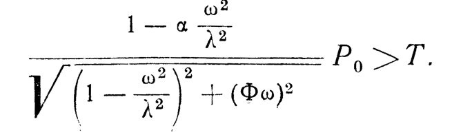
If we neglect the influence of the system’s own weight, which in real conditions most often makes up a relatively small fraction of the vibrator’s disturbing force, then the failure condition for model No. 1 consists in fulfilling the inequality:

In other words, in order for the failure to take place in the No. 1 model, it is necessary that the amplitude 
For Model No. 2, the breakdown condition was presented by Yu. I. Neimark in the form:

where
- c is the total coefficient of spring stiffness 3;
- A is the amplitude of pile oscillations.
Until the breakdown occurs, the oscillation amplitude can be determined from the well-known expression:

where
is the natural frequency of the pile (M is its mass);
damping modulus according to N.P. Pavlyuk [47].
Substituting this value A into inequality (1. 2), we will have:

It can be seen from this that in model No. 2, the stall condition essentially depends on the frequency ratio 


It is easy to show that the regularities described above, obtained by considering the stall phenomenon on model No. 2 are very far from reality. To do this, it suffices to obtain the breakdown condition for a more rigorous model No. 3. If we denote the mass of the body 5 (the “unsuspended” mass of the soil) as m, and the ratio of this mass to the entire mass M + m of the system as a, then the breakdown condition in this case will have the form:
Here

Denoting the expression before 


where 


 coefficient versus ratio.
It can be seen from the graph that taking into account the influence of the soil mass significantly changes the stall conditions. In the preresonant region, there is indeed some increase in the coefficient 


The greater the value of 

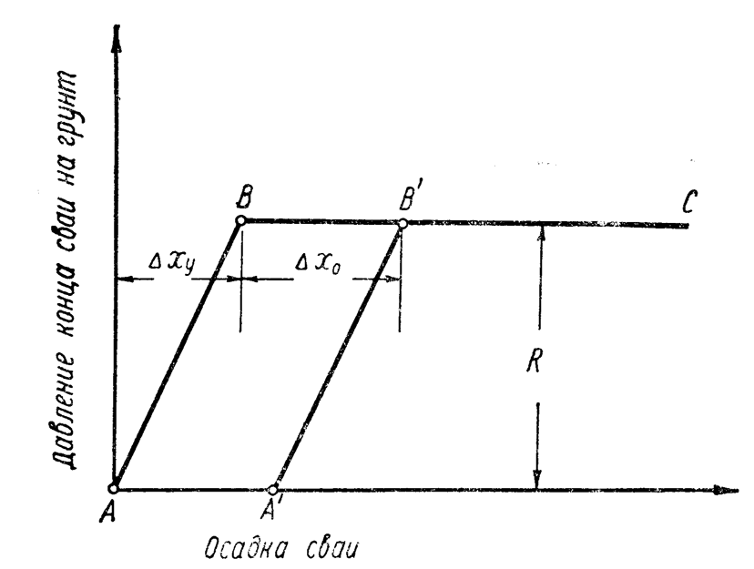

Consider the mechanism of pile drag in models No. 2 and No. 3, built taking into account the influence of elastic deformations of the soil. The dependence of the pile settlement on the pressure of its lower end on the ground, corresponding to the diagrams shown in Figures 20b and 22, is shown in Figure 24; just as in the graph (Figure 20), the value of the draft is plotted along the horizontal axis, and the pressure is plotted along the vertical axis. In section AB, elastic reversible deformation of the soil occurs (compression of the spring), in section BC, irreversible punching (slump of the plug.) If, by increasing the pressure on the ground, then at point B’ the load is removed, then the restoration will go along the segment B’ A’.
Yu. I. Neimark points out [37] that the value of irreversible soil punching 
where 
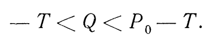
It follows from this expression that a decrease in the value of R increases the punching, and an increase in
In construction practice, we usually meet with the case when the toe resistance to pile driving exceeds its weight (R > Q.) Obviously, in this case, successful immersion, even in the presence of a complete stall, can be expected only when the amplitude A of the pile vibrations exceeds its elastic settlement 
Using the previous notation, it is easy to represent the inequality 
where 
From this it can be seen that at low frequencies 


Dependence (1. 6) determines the upper limit of the ratio
There is currently no solution to the problem of vibrational driving of piles, taking into account the influence of inertia and elasticity of the soil (model No. 3.) The problem for the case of a weightless elastic soil (model No. 2) was studied by Yu. I. Neimark approximately by the harmonic balance method and by M. Ya. Kushul and A. V. Shlyakhtin by the method of initial parameters. The solutions they obtained, differing in considerable complexity, due to the use of a very rough assumption about the weightlessness of the soil, are interesting only because they make it possible to qualitatively assess the effect of soil elasticity on the process of vibrational immersion. In the simplest setting (on model No. 1), the problem under consideration was solved by Yu. I. Neimark and I. I. Blekhman, who derived relatively simple calculation formulas to determine the maximum depth, average speed and time of pile driving. The latter formulas are sufficiently accurate in those cases of greatest practical importance, when the amplitude A of the pile oscillations and the speed v of its immersion are sufficiently high; according to Yu. I. Neimark, this condition can be considered satisfied when

Due to lack of space, there is no way to dwell on the features of the methodology and the course of solving the problem even for the last simplest case. Referring the reader who wants to learn more about this solution to the works of Yu. I. Neimark and I.I. Blekhman, we confine ourselves to listing the final formulas obtained by these authors for this case.
According to Yu. I. Neimark. the pile oscillation amplitude can be determined from the approximate expression:

where K is the eccentric moment.
Considering this expression, one can see that in those cases when the force T of lateral friction turns out to be significantly less than the amplitude 
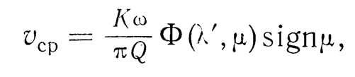
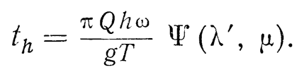
To determine the average pile sinking speed 
Note: vcp and vsr are the same
where 

- Q is the total weight of the submersible system (including static load, if any);
is a function of dimensionless parameters
and
, the graphs of which are shown in Figure 25.
In Equation (1.9), the symbol sign denotes a quantity equal to 1 for 


Within the limits adopted when building the model No. 1 of the initial assumptions, Equation (1. 9) is accurate only in the absence of toe resistance of the soil (R = 0), which occurs, in particular, during vibration recovery. In the presence of drag, the formula gives a somewhat underestimated value of the sink rate.
In the case of vibration penetration, the average velocity
Finally, we note that Equation (1.9) can be used to calculate the speed of vibration penetration only if the conditions

and for calculating the speed of vibroextraction – under the conditions
If these conditions are not met, then there is either relative rest (
For small

However, already for 

It follows from Equations (1.9) and (1.12) that the average pile sinking speed, other things being equal, is directly proportional to the oscillation speed, which generally agrees with the available experimental data.
I. I. Blekhman also proposed a formula and an auxiliary graph for calculating the time 
Equation (1.13) is obtained by integrating dependence (1.9) under the assumption that the toe resistance does not depend on the immersion depth h, and the lateral resistance depends on h according to a linear law:
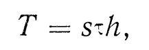
where
is the friction force per unit area of the surface of the submerged element;
- s is the perimeter of its cross section.
Graphs of the function 

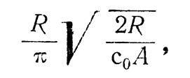
The maximum depth 

During vibrational immersion, the friction of the pile against the ground and the resistance of the soil to punching are overcome (the work spent on excitation of vibrations of the soil mass is not taken into account by model No. 1.) The power required by the vibrator is:

In cases where the conditions (1.7) are not met, the elasticity of the soil begins to play a significant role.
The pile sinking speed under the influence of soil elasticity a decreases, and on the graph of the dependence of the sinking speed v on the amplitude of the pile oscillations A, a section appears where 


where 
The results of theoretical studies discussed above made it possible to significantly refine our ideas about the mechanism of the process of vibrational immersion. They can be successfully used for comparative evaluation of the efficiency of vibratory drivers of various types, as, for example, O. I. Schechter in his work [66].
This is the main value of the available theoretical work.


2 thoughts on “Existing Proposals for the Theory of Vibratory Pile Driving”