

To access the rest of the book, click here.
Editor’s Note: for the most part this concerns a topic that U.S. contractors would consider drilled shafts. (The term here is “filled piles;” the literal translation of the Russian term is “stuffed piles,” which driven pile people might find amusing, but I thought it would be better to stick with what I did.) Even in the U.S., however, vibratory pile drivers revolutionised the installation of drilled shafts by their ability to drive and extract casings for drilled shafts in soils where a clean, self-supporting hole was not possible. The Russians added to this considerably and their results should be considered.
One of the challenges of editing the translation (whether done by humans or computers) is in sorting out the differences in terminology between Russian and American usages. In many cases I’ve left the Russian translation as literal as I wasn’t quite sure what they were talking about. Two items, however, deserve special mention: the degree of saturation (which the Russians refer to literally as humidity,) and the “consistency index,” which the notation they use indicate that what they’re talking about in reality is what we would call the liquidity index. Some light on this topic is given by Tsytovich, which I used to justify the translation:
Consistency may be characterized by the relative consistency B (according to BC&R) or the liquid index IL (according to the international classification), the latter being determined by the expression
According to BC&R, the following kinds of consistency of clays are distinguished depending on the magnitude of IL:
Soil Mechanics by N.A. Tsytovich
- Hard: IL < 0, i.e., when W < Wp
- Semi-hard: IL= 0-0.25
- Stiff plastic: IL = 0.25-0.50
- Soft plastic: IL = 0.50-0.75
- Liquid plastic: IL = 0.75-1.0
- Liquid: IL > 1

When solving the problems of capital construction, one of the central places is occupied by questions of saving metal and concrete. At the same time, the loads from the built structures are growing. This explains the inevitable tendency to increase the load bearing capacity of the piles. Filled piles, in our country, account for approximately 15% of the total volume of all types of piles; abroad, approximately 40%.
In the manufacture of filled piles, various types of equipment are used. Experience shows that the use of specialized machines manufactured by Kato, Benoto and the domestic BSO machine is economically justified when constructing deep-laying supports in particularly difficult geological conditions. At the same time, in the mass production of filled piles in more or less homogeneous soils, the disadvantages of this equipment are revealed – its high cost and bulkiness with low productivity. It is known that under such conditions, high productivity is provided by domestic CO-2 screw rigs designed for drilling shafts in cohesive dry soils with a diameter of up to 600 mm with a broadened base. With an increase in the diameter of the shaft, the auger working body is replaced by a drilling cylinder (installation SO-1200) and the productivity of penetration is significantly reduced due to the increase in cyclicity.
A special place is occupied by the use of filled piles prepared using vibration technology. Such piles have a number of advantages over bored piles. Among the main among them is the possibility of making piles in water-saturated soils without leaving pipes in shafts and application of sedentary concrete mixtures, which allows you to get significant cement savings and high quality molded piles due to the effective compaction of the concrete mix at vibration influences. In addition, the use of vibration technology allows increase labor productivity when drilling shafts, immersion of inventory pipes, and reduce effort their extraction after filling it with concrete, which, in turn, makes it possible to reduce the carrying capacity of the crane equipment and in most cases general construction cranes can be used for the manufacture of filled piles.
The use of foundations from filled piles manufactured vibration equipment are most suitable for frame buildings and structures with the design load on the foundation more than 1000 kPa, buildings with load-bearing walls – more 400 kPa, supports of technological pipelines and other similar structures.
Filled piles, manufactured using vibration technology, should be used in loose and medium density sandy soils, regardless of moisture content and grain composition; in clayey soils, including loess, soft and hard-plastic consistency, as shaft as when cutting through the specified soils and supporting piles on dense sandy, hard clayey, coarse-grained, semi-rocky and rocky soils.
Depending on the geological conditions, filled piles with the help of vibration technology can be made with or without excavation, and depending on the degree soil moisture, without casing and with casing of the shaft inventory pipes.
| Soil type | Pile diameter, mm | Pile length, m | Type of equipment | Pile manufacturing technology | |
| shaft equipment method | Concreting method | ||||
| Unstable sandy and clay soils | 325-377 426 530 | 3-10 3-12 3-15 5-10 5-15 5-12 | B-401 VP-l PVN-l PVN-l PVN-l PVN-l | With retrievable casing pipes without excavation | Dry low-slump or moderately stiff concrete mixes, compacted During casing retrieval |
| 630 720-1020 | 5-15 5-20 8-14 10-20 | BVS-1 VP-1 VP-1 PVN-2 | With retrievable casing pipes and excavation | The same or the VPT method with vibration | |
| Stable clay soils | 426 377 | 5-15 3-15 | PVN-l PVN-l | Without excavation | Dry sedentary or moderately hard concrete mixes with layering with a vibrating grab or vibrator |
| 380-500 530 (800) 820-1220 | 3-15 5-20 8-25 | PV-380 PV-530 PV-500 PV-820 | Without casing pipes, with excavation | ||
When designing and installing filled piles according to vibration technology, it is recommended to use departmental building codes VSN-309 – 84/MMSS USSR
The choice of the method of manufacturing piles and vibration equipment produced depending on the ground conditions and the existing loads in accordance with Table 17.
Lifting equipment for work on the installation of filled piles with vibration machines, pile drivers and self-propelled jib cranes with the appropriate lifting capacity, hook lifting height and winch rope capacity, as shaft as percussion-rope drilling machines, can be used.
When working with vibratory drivers of all types, the load capacity crane at the working reach should be at least doubled relative to the vibration system (vibrator, shock absorber, headrest, casing.)
When using the BVS-1 impact-vibration hammer as load lifting equipment, shock-rope machines are used drilling UGB-3UK (UKS-22) and UGB-4UK (UKS-30.)
Lifting height of the lifting hook on the working reach is assigned equal to the total height of the system, consisting of a shock absorber, a sling, a vibration unit and casing section, plus 1 m. Rope capacity of the crane winch must ensure the lowering of the vibrating grapple soil intake below the design level of the shaft by 1-1.5 m, taking into account the length of the sling and the height of the vibratory grapple.
Power of transformer substation and supply network must be at least 100 kVA for vibrating grabs and vibration hammer BVS-l and at least 200 kVA for vibration installations such as PVN, vibratory hammers V-401 and VP-1.
The diameter of inventory casing pipes is assigned according to according to the diameter of the manufactured filled pile.
In the manufacture of filled piles without excavation using vibratory installations PVN-1 or vibratory pile drivers B-401 uses casing pipes with a diameter of 325-530 mm with a wall thickness of at least 8-10 mm.
Works on driving shafts for filled piles using vibratory grabs must be carried out using guide devices. The size of the vibratory grapple should be choose depending on the size of the passable shaft. The dimensions of the section of the soil intake of the vibrating grapple must correspond to the design section of the shaft. At the same time, it is necessary take into account that the minimum diameter of passable shafts determined by the diameter of the vibration mechanism.
When selecting a vibrating grapple for extracting soil from casing pipes, it must be taken into account that the diameter of its soil intake must be at least 100 mm smaller than the internal casing diameter.
The dredgers of the vibrating grabs are equipped with interchangeable cages, the section of which is chosen depending on its diameter and type of excavated soil.
The choice of concrete casting equipment depends on the accepted method of concreting; for this, it is necessary to have a loading funnel, a receiving tub, and when concreting shafts without casing protection, deep vibrators.
The mixture can be transported to the site by mixers or dump trucks. In this case, it is unloaded directly into the feed funnel or receiving buckets.
Production of filled piles with excavation without casing shafts are carried out with the help of vibrating grabs, which it is advisable to use when working in sands with a degree of saturation (0.2 < S < 0.5), dense and medium density, in clay soils with liquidity indices 0 < IL < 0.6, strong and medium strength, loess and loess-like soils.
Drilling a shaft should begin with the installation of a guide device and checking its location along the axis of the shaft.
The vibrating grab is installed in the guide and immersed in the ground under the action of longitudinal vibrations. Filling the soil collector should be stopped at a significant slowing down of the immersion speed of the vibratory grab.
At the initial stage of extraction of the vibrating grab, before separation ground core, the lifting speed of the load hook should be minimal. In case of insufficient load capacity of the equipment it is necessary to include rotational vibrations that reduce the extraction force of the vibrating grab.
Soil unloading is carried out with rotational or longitudinal fluctuations until the complete release of the soil intake from the ground. After driving a leader shaft with a depth of 1.5-2.0 m guide device is removed and rearranged on the axis next shaft. Drilling a shaft to the design mark continue by repeating the indicated operations. Works on the manufacture of filled piles are carried out in accordance with the technological scheme shown on Figure 69. At the same time, the last 1.5 m of the shaft is drilled immediately before concreting.
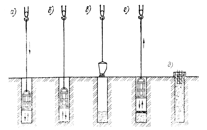
Stages of work on the production of filled piles with a vibrating grapple are shown in Figure 70. Vibrating grabs allow carry out excavations in the ground for the device supports of complex configuration in plan. Rectangular penetration in terms of production, in principle, there is no difference from drilling conventional shafts.
The workings of a more complex section are carried out using leveling racks that serve as delimiters between passed and developed parts of the working and protect the vibrating grab from blockage. as guides racks, it is necessary to use beams of profile section (I-beams, channels, etc.) or pipes with welded to them metal pieees with a width equal to the working width. The lower part of the racks is installed on the working face, and the upper part is fixed from shifts. If necessary, shaft bottom sealing is produced with longitudinal vibrations in 15-30 s cycles using a tamping bottom, which is attached to the soil collector instead of the nozzle. After compaction of the bottom hole, perform a visual inspection of the shaft.

Laying of low-slump concrete mixtures in the shaft is carried out by free dropping through a receiving funnel and layer-by-layer compaction of concrete using a deep vibrator.
The following are examples of the manufacture of filled piles with vibrating grabs at the facilities of Belarus (V. E. Trofimov, V. M. Polotsky, 1977.)
In Minsk, the Belarusian specialized trust “Promburvod » at the construction of a residential building: while using a vibrating grapple PV-500 produced 116 filled piles. The vibratory grabber worked together with the E-1258 crane. The construction site was composed of wet sandy loams, passing at a depth 3.5-4 m into loams underlain by coarse-grained sands. The total time of drilling one shaft with a depth of 5 m, taking into account auxiliary operations and technological downtime was 15-20 min. Soil was unloaded outside construction site, which significantly reduced the volume of subsequent earthworks.
In Mozyr SSMY-4 of the same trust used a vibrating grapple PV-500, installing 260 filled piles with a diameter of 530 mm, based on dense moraine loams containing boulder-pebble deposits. No shafts were possible with carry out penetration at this site, since the presence of stony inclusions led to to jamming of augers and failure of the unit. Medium speed of drilling of shafts by vibrating grapple PV-500, working with a crane SMK-10, amounted to 10 m/h. Soil from a vibrating grapple unloaded onto a light conveyor, the use of which made it possible to concentrate the entire volume of excavated soil in certain construction sites, which in the future reduced the complexity of the work to remove it.
On another object in the city of Mozyr, a vibrating grapple was made in sandy loamy soils for 100 piles with a trunk diameter 530 mm and laying depth up to 12 m. Average penetration rate shafts was 12-13 m/h. All device operations filled piles were produced with the help of an truck crane with a lifting capacity of 10 tons.
The experience of arranging filled piles with a vibrating grapple showed that that with a very simple technology, a minimum number employed workers and when using one lifting crane achieves high productivity.
Production of filled piles with excavation under protection casing pipes are carried out using installations of the type PVN-2 complete with vibrating grapple, For immersion of casing pipes can also be used vibrator VP-1 and impact-vibration hammer BVS-l.
The specified equipment is advisable to use in sandy soils of all types, with a degree of saturation 0.5 < S < 1 and in clay soils with a liquidity index of 0.5 < IL <0.75.
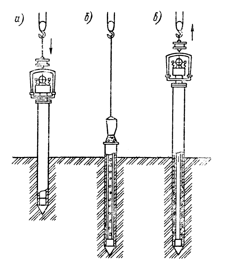
Works on the manufacture of filled piles with excavation and under the protection of the shaft with casing pipes to the full depth are carried out in accordance with the technological scheme given in Figure 71.

To the head of the vibrator, located in the horizontal position, with the help of a lifting device, a casing section is attached, and a spring shock absorber to the suspension . The whole system is raised, and the lower end of the casing pipes are installed along the axis of the future filled pile.
When turning on the unit and gradually lowering the hook hoisting equipment, the casing is immersed pipes either to the design elevation or a significant reduction (0.1 m/min) in pipe speed, which indicates the formation of a soil plug.
If during the immersion there is a violation of verticality of the casing pipe, the process should be suspended, the system raise once or twice to a height of 0.5-0.8 m, followed by a new lowering.
In cases where the upper layers of the soil can provide stability of the shaft walls without casing, it is advisable before by immersing the casing pipe to carry out the penetration of the leader shafts vibrating grapple to the full depth of sustainable zones. Upon reaching the design mark or a significant decrease casing sink rate excavation from its internal cavity is produced by a vibrating grab.
Extraction of soil from casing pipes submerged by the installation PVN-2 is made through the through hole provided in her design.
When working with the installation PVN-2B [24] vibrator BP-l or BVS-1 impact-vibration hammer before soil extraction, removal of the vibration exciter from the casing is provided. After removing the soil, the vibration exciter is reattached to the casing pipe, which, if necessary, will achieve the design elevation or to the next stop.
Before installing the reinforcing cage, inspect the shaft and, if necessary, clean the surface of the casing pipes and bottom hole. In the event that there is no water, the remaining loosened soil is picked up with a vibrating grab. If there is sandy soil at the bottom, it is compacted by the tamping bottom of the vibrating grapple. In clay soil gravel or crushed stone mixture can be rammed. If there is an insignificant layer of water (0.5-1.5 m) at the bottom, it must be pumped out or lay a thin concrete mix. If the water level at the bottom of the hole is over 1.5 m and it cannot be pumped out or otherwise removed, filling shells with concrete mixture must be produced by the method VPT with vibration in accordance with the requirements set out in SNiP III -15-76.
Pile concreting is carried out by inactive concrete mixtures that can be loaded into the casing either all at once to the full height, or in portions.
In the process of extracting the casing, it is necessary to constantly keep an eye on the shock absorber, avoiding full compression its springs. Each casing retrieval cycle should precede her vibration without lifting for 1-1.5 min. In cases where the main load on the pile is perceived side surface, casing removal produced with periodic settling.
Vibration unit PVN-2B is shown in Figure 72. As an example of the use of the PVN-2 vibration unit when installing filled piles consider the experience of pile foundations in gravel soils during the construction of lighting poles masts of the Olympic complex of the stadium “Dynamo” in Minsk.
It should be noted that using longitudinal vibrators and hammers to drive piles into gravel soils is usually very difficult or impossible.
When using the PVN-2 vibration unit at this facility (B. B. Rubin, 1980) an inventory shell with a diameter of 720 mm and 12 m long was equipped with teeth on the lower end, which allowed under the action of a longitudinal-rotational perturbation gave the shell a unilateral rotation, in which it moved the gravel apart and plunged to a predetermined depth with average speed 0.7-1 m/min. When concreting the pile shaft an inactive concrete mix M-300 with sediment cone 6.0 cm was used. The compaction of the concrete mixture took place in the process of vibroextraction of the casing pipe.
As a lifting device in the manufacture of rammed piles with the PVN-2 installation, a DEK-25 crane was used. Filled piles manufactured at this facility were used as foundations instead of bushes made of prismatic piles with a section of 30 X 30 cm, 9 m long. Pile heads according to the project united by a monolithic grillage 1.5 m high. As a result the use of filled piles resulted in savings in concrete by 3.4 times and reinforcing steel by 4.7 times.
The stage of work with the BVS-1impact-vibration hammer at installation of filled piles with a diameter of 630 mm and a length of 18 m shown in Figure 73.


The disadvantage of filled piles of solid section is high consumption of concrete per unit of bearing capacity. This consumption is not related to the need to ensure the bearing capacity piles according to their material, which, as a rule, significantly higher than the bearing capacity of piles on the foundation soil and is caused by traditional pile manufacturing technology.
In a number of cases, when the determining factor in the bearing capacity of piles is their resistance along the lateral surface or when piles work mainly on horizontal and moment loads (in enclosing structures, anti-landslide structures, etc.,) piles of an annular cross section are most appropriate.
A technology has been developed for manufacturing filled pile-shells in stable soils using a vibrocore (V. I. Berman, 1979). A vibrocore is a conical projectile of tubular sections connected to each other through elastic gaskets. Inside each section there are vibrators of circular oscillations, the axis of which is parallel to the axis of the vibrocore. The inclusion of each vibrator is individual from the remote control panel. A bunker feeder is mounted at the wellhead to receive the concrete mixture, and a reinforcing cage with guide brackets is installed in the shaft, ensuring the frame is centered relative to the transverse annular section of the pile, and concreting is carried out to a height of 23 m. A vibration core is installed, the vibrators of the lower section are turned on and the concrete is vibrocompacted so that the solid foot of the pile is at least 0.7 of the pile diameter in height. Then the concrete mixture is vibrated in the remaining part of the shaft. Turning on the vibrators alternately, the shaft is completely filled with concrete. After that, the concrete mixture is vibrocompacted for 5-8 minutes, after which all vibrators are turned on and the vibrocore is removed. The vibrators are turned off when the vibrocore reaches 0.5 m. Then a solid section shaft is arranged in the upper end of the pile with a length equal to its diameter, and a pile is formed. This operation can be combined with a grillage device. The length of the vibrocore is 12 m, the diameter at the top is 530 mm, at the bottom 430 mm, the rated power is 6 kW. This technology has been introduced by the trust Ukrburvod of the Minmontazhspetsstroy of the Ukrainian SSR at a number of facilities in Kiev/Kyiv. Reducing the consumption of concrete in this case in comparison with filled piles of a solid section – from 30 to 40%. The disadvantage of the technology is that it is feasible in stable soils, which narrows the scope of its application.
Production of filled piles without excavation under protection casing pipes are carried out using installations type PVN-l, vibratory drivers of types V-401, VP-l or vibratory hammer BVS-1 type.
Filled piles of this type can be made by immersing a casing pipe with a loose or self-expanding shoe in sandy soils with a degree of saturation of 0.5 < S < 1 and clay soils with a liquidity index of IL > 0.5, or by punching a hole with a pipe with a cone tip in sandy soils with degree of saturation S < 0.5 and clay soils with a liquidity index of 0.25 < IL <0.5, as well as in loess soils.
Works on the manufacture of filled piles without excavation but with a lost or drop-down shoe are carried out In accordance with the technological scheme shown on Figure 74. When installing such piles in a recess with a depth of 30-50 cm, formed along the axis of the pile, a lost shoe is installed. Several turns of tarred rope are wound on its cylindrical part, which prevents water from entering into the tubing. When installing piles with a drop-down shoe, a locking lost ring is put on the lower part of the blades brought to their original position.

A pre-assembled vibrating system with lifting means is installed vertically on the lost shoe. When working with the installation PVN-1, the initial stage of immersion casing pipe is produced in vibrating mode. After lowering the immersion rate to 0.1 m/min, further casing pipe is immersed in impact-vibration mode. Mode switching is carried out using a special device.
After the casing pipe is immersed to the design elevation the vibrator is disconnected and into the internal cavity pipes are installed a reinforcing cage. Casing to the full height is filled with a slow-moving concrete mixture and is extracted by vibration, there being a lost (or revealed) shoe.
If necessary, for ramming concrete into walls shafts in the process of extracting the casing pipe can be produced its periodic precipitation by 0.5-1.0 m.
The casing pipe lifting speed is taken within 0.5-1.0 m/min; the lifting process should take place without sudden jerks and stops to avoid breaks in the continuity of concrete and formation of voids. For the last 1-1.5m of lifting, the casing pipe is retrieved by the static force of the lifting device.
In the manufacture of filled piles without excavation by the method shaft drilling, the casing pipe must be closed with a cone tip welded to its lower end. Casings are extracted in the vibration mode, and lifting speed is limited only by the lifting capacity shock absorber, the turns of which should not compress solid. At reducing the effort to extract the pipe to a value equal to or lower lifting capacity of the crane at a given reach, the pipe is lifted further with the vibration exciter turned off.
High technical and economic efficiency of vibrating piles with a diameter of up to 377 mm, immersed without excavation soil, was established by D. D. Barkan, O. A. Savinov, E. V. Svetinsky, E. M. Perley, and A. M. Rukavtsov. The further spread of these piles in construction was hindered by the insufficient immersion and extraction capacity of the existing vibration equipment.
The scope of the most effective filled piles without excavation can be significantly expanded if using specialized installation of impact-rotary actions of type PVN-1, with the help of which filled piles up to 530 mm in diameter and laying depth 16 m [12].
Figure 75 shows the stage of the installation of filled piles by installation PVN-1, which was successfully used at the facilities trust “Ukrhydrospetsfundamentstroy” and Trust 15 of the Ministry of Construction of the Belorussian SSR.
The quality control of the production of filled piles was carried out in accordance with VSN-309 – 84 / MMSS USSR.
Vibratory technology for sand ramming piles is similar to the concrete manufacturing technology described above for filled piles, but it is simpler, since for the manufacture sand piles in all cases, you can use the inventory a pipe equipped with a drop-down tip, which does not need to be sealed.
The method of deep compaction of weak soils with sand piles became widespread due to the use of the vibromethod. A new technology has been proposed and developed D. D. Barkan with the participation of E. V. Svetinsky, and. S. Gutsalenko and others (1953.) This technology has been further developed thanks to the work of E. V. Svetinsky.
Vibrator for deep compaction of weak soils and sand piles usually consists of a crane on a crawler running, vibrator with shock absorber, casing pipe with head and an inventory self-expanding shoe. Below cap on 0.3-0.5 m, the pipe has a hole through which it is filled with sand. The length of the pipe should be 10-15 % more than the length of the sand piles (taking into account the compaction of the aggregate) .
The drop-down shoe designed by T.F. Rybin consists of four petals hinged to the pipe, which are held in a closed position by a ring during immersion and filling with sand. When the pipe is pulled out, the ring jumps off the end of the shoe, the petals open and the pile filling material fills the hole as the pipe is pulled out.
Vibratory sand pile technology includes three main operations: vibratory immersion of the pipe, filling it with sand-gravel mixture and vibratory extraction. As the diameter of the sand piles increases, compaction radius and fewer piles are required, In construction practice, sand piles are mainly used using casing pipes with a diameter of up to 377 mm, which limited by the immersion capacity of the vibrator VPP-2 (B-401.)
According to research by Yu. M. Abeleva (1954), when constructing sand piles, pipes with a diameter of 400-500 mm should be used. For immersion of pipes of such dimensions, the above-described vibratory hammers PVN-1 and VSh-I can be successfully used.


2 thoughts on “Manufacturing Piles Using Vibration Technology”