

CHAPTER I
INTRODUCTION
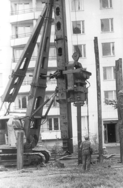
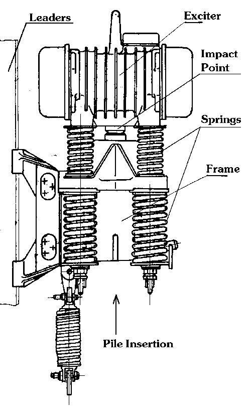
The term “impact-vibration hammer” refers to a type of vibratory pile driver that imparts both vibrations and impacts to the pile during operation. Such a machine is shown in Figure 1. Figure 2 shows a diagram of the internal construction of an impact-vibration hammer. At the centre of the machine is an exciter with two eccentrics, powered by motor(s); however, instead of being clamped or otherwise rigidly attached to the pile, the exciter is connected with the pile via springs. During rotation the eccentrics rotate oppositely from one another; the eccentrics are synchronized by the motion of the machine. This is possible because the flexibility of the springs insures sufficient amplitude to accomplish this; this is not always the case with vibratory hammers. The frequency of vibration is equal to the rotational speed of the eccentrics; the amplitude of vibrations is given by the ratio of the eccentric moment to the exciter’s weight.
When the distance between the anvil and the vibration exciter is less than zero, the exciter strikes the pile and rebound lifts the exciter upward. With the help of the spring mechanism it is possible to increase or decrease the impact frequency of the vibrator. The impact frequency can, for instance, equal the vibrating frequency of the exciter, or the exciter can strike the pile every second, third, fourth, etc. rotation.
These springs transmit their compression force, which is of a vibratory nature, to the frame; in addition to this, depending upon the position of the head relative to the impact point and the effect of the springs on the vertical motion of the head, at or near the bottom of the vibratory cycle the head strikes the anvil and produces an impact similar to traditional impact hammers, but at a higher blow rate. Although this can produce variations in the eccentric rotational speed of up to 40% (as opposed to the 5% or so normal for vibratory hammers), this variation generally does not impede the continuous, stable operation of the equipment. Impact-vibration hammers also exist that produce impacts at both the top and bottom of their stroke, which has proven beneficial in their ability to drive and extract piles.
Impact-vibration hammers are different from purely vibratory ones because they can tune themselves to the conditions of the driving system. They can vary their striking energy with the increase in driving resistance, or with the softening of the striking point. The characteristics of the machine can be influenced by the mechanical coefficient of speed restoration, which describes the relationship between the impact and rebound speeds of the exciter. This coefficient depends upon the weight ratio of the exciter to the pile. During driving any resistance increases the effective coefficient increases, and so the striking energy. This phenomenon appears in classical impact hammers as well and gives the possibility for efficient use of the machine.
Since the exciter moves in the frame, the construction of the frame determines how the machine is connected with the pile, if at all. The frame can be connected to the pile in numerous ways, with several types of clamps, or not at all, using the frame weight to keep the hammer in place during driving.
2 Categories of Impact-Vibration Hammers
Impact-vibration hammers can be categorized in various ways. They include the following:
 |
Nature of energy input into the machine (pneumatic, hydraulic, electric, directly with internal combustion engine); |
The usual electric impact-vibration hammer without a transmission consists of three basic parts: 1) exciter, 2) springs, and 3) frame (see Figure 2.) The two eccentric exciter has a steel frame with two cylindrical holes, and their axes are horizontal. Stators are pressed into these holes, fixed against moving with bolts. Bearings with two rows of spherical rollers are mounted into special block mounts. The striking point is located in the lower part of the exciter, riveted to the exciter. There are mounts for the springs which support the exciter, depending upon its construction.
The use of transmissions from motor to exciter is employed to protect the motors from damage, as they are difficult to replace.
|
Nature of connection of engine or motor with eccentrics (direct or through some type of transmission); |
With most electric machines, the rotors are pressed onto the shafts rotating in the bearings. The eccentrics are situated on the end of the shafts. In this way the eccentrics are directly driven by the motor. If a transmission is used, the transmission must endure the impacts.
|
Type of elastic connection between exciter and frame (with or without springs); |
The frame is connected with the exciter with an elastic element. These vary in material and stiffness. Any frame will have an anvil in the upper part which serves to transfer the force of impact from the exciter to the pile. Impact-vibration hammers with springs are used when specific circumstances are encountered (such as a requirement to extract the piles,) but if these hammers can be used without springs than it is advisable. High frequency impact-vibrators can only be used in soft soils and with low displacement piles.
|
Type of connection between the frame the pile (clamped or free.) |
Impact-vibration hammers are categorized according to the way in which the frame is connected to the pile. With these machines, a secure connection to the pile enables the machine to use the exciter to push and pull against the pile, thus using the pile to anchor the machine. A frame which is rests unconstrained on the pile has the possibility of moving in the direction of the exciter during operation. To deal with this, the frame’s weight is chosen with the potential force of the exciter springs in mind. If the frame weight is greater than the force of the springs, the frame will not move and thus provide a stable work environment for the exciter.

Figure 3 shows various methods by which the exciter interfaces with the frame and the frame with the pile.
An anvil is captured inside of the body of the frame, and is interfaced with the pile. To handle the machine, the frame has a lifting bale to which a cable can be fastened to lift the machine. In some cases the frame has a device to adjust the transmission of dynamic loading from the exciter to the frame.
Specifications for a wide variety of impact-vibration hammers are shown in Appendix B; from Russia, Table I, from Japan, Table III, and from Poland, Table IV.
In Japan two firms manufacture impact-vibration hammers, Nippei and Toyota. Of the Nippei units, the NVH-30 and -50 are used for pipes and other piles in both driving and extraction; the two machines are similar in construction, but the anvil configuration of the NVH-30 gives the possibility of an upstroke. The Toyota hammers are all electric and similar in construction throughout the line.
3 Sheet Pile Extractors
Although it is theoretically possible to use conventional impact-vibration hammers to extract piles, modified driving machines are not effective in every case. For example, they are not effective when the pipes or sheet piles have been in the ground for a long time, or in frozen soil. In these cases the soil resistance is much higher than the driver’s ability to overcome it and extraction becomes virtually impossible.

Impact-Vibration Sheet Pile Extractor (SP-83)
A special type of impact-vibration equipment used with sheet piles is the sheet pile extractor. In these machines the impact is upwards and imparted indirectly to the extracting element, and the spring reaction is downwards. The amplitude is sinusoidal and the striking impulse takes place in a small time interval and reaches considerable size. An example of this type of machine is shown in Figure 4.
When impact-vibration drivers and extractors for sheet piles are compared, for the same weight the extractor allows the removal of piles 150% longer and heavier than modified drivers. In many of thee machines, to decrease the vibration transmission to the hook or boom, a mass-spring vibration dampener is used, similar in principle to the suspension systems of vibratory hammers.
As a group impact-vibrations machines for extracting sheet piles are more common from year to year. In Russia three types of these machines are manufactured; their specifications are given in Appendix B, Table V.
One of the main features of any sheet pile extractor is the clamping system. For example, model VI-592A has two types of pile clamps. Mechanical cam clamp (Figure 5) consists of a cam, which is assembled in the relatively vertical axis of the frame in its lower part, a system of hinged strips and levers (2) which simultaneously rotate the two eccentric jaws, the spring latch (3), which keep the jaws through the latch system in the extreme up position.
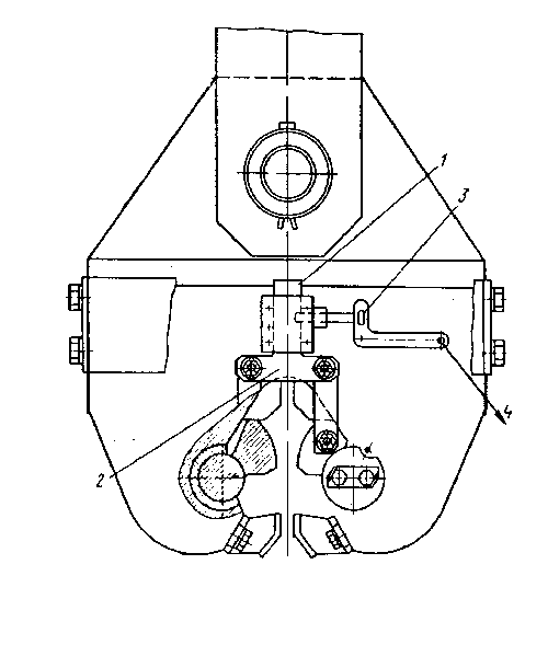
Mechanical Cam Clamp (after Shirai (1978))
The cam locking system works in this way. The clamp is lowered to the pile top so that the two jaws are on both sides of the web of the pile. The very top of the pile is placed firmly on the horizontal connector. This lifts the whole mechanism into place with the jaws up; the jaws are kept up by the spring latch system of the mechanism.
Before starting the extraction latches are released by pulling rope (4). At this time the jaws rotate and pull the mechanism down; extraction further tightens the jaws grip on the pile. After the pile is removed from the soil as much as desired, the weight of the hammer is applied to the pile top through the lever system; the horizontal bar is pushed upwards and the clamp is released. This also puts the mechanism in the up position, preparing it for the next pile.
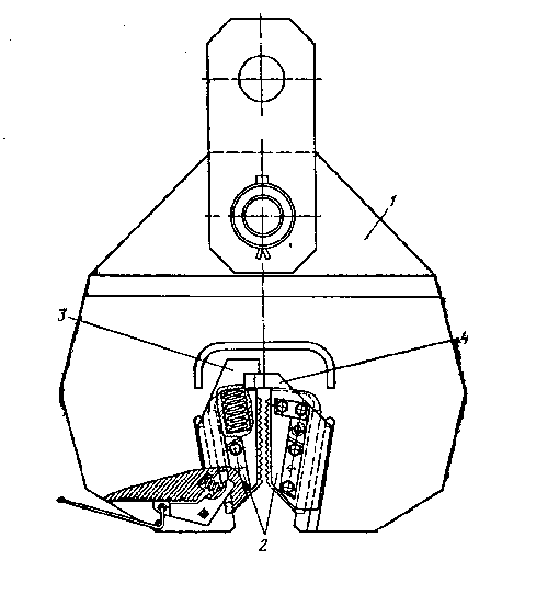
Wedge Type Clamp (after Shirai (1978))
When the top of the pile has been severely deformed during driving or other sources of damage, the wedge type clamp (Figure 6) is used. This differs from the cam type because of the wedge shaped slot in frame (1), which narrows downward. In this slot there are two wedge shaped spring loaded jaws (2), one of which has a projection on the top and the other one a slot, which insures that the jaws are properly synchronized.
Strips are placed to insure that the jaws do not fall out of the clamp; these strips also insure that the jaws stay in their tracks.
When the clamp is lowered onto the pile top, the jaws are moved upward until the ledge (4) rests firmly on the pile top. The springs force the jaws into the sides of the pile web; when the hammer is started the jaws are tightened on the pile. This connection is tighter than the cam type. When extraction is complete, the hammer is lowered and the jaws release themselves.

Extractor VI-809 with Wedge Type Clamp
Figure 7 shows this type of clamp on an impact-vibration sheet pile extractor, in this case a model VI-809.
The most common types of sheet pile extractors in the construction industry are models Sh-2 and MSh-2M, with technical characteristics given in Appendix B, Table V. Extractor Sh-2 is a modified impact-vibration driver (the exciter’s type is the same as V1-592A) but does not have holes in the motor. The exciter is situated in a small closed frame, with a vibration dampener fixed to the top, and the clamp is on the bottom. The exciter is connected with the frame through four pairs of springs; on the upper part is situated the striking point with matching anvil on the frame. The exciter’s stroke is transmitted to the frame and then through the clamp to the sheet piling to be extracted. Extractor MSh-2M is a successor to Sh-2 for larger piling.
The powering of a sheet piling extractor, be it electrically or hydraulically powered, is carried out with the help of a special control paned, which contains the electric starting device, thermal protection, and devices to monitor the parameters of the extractor. The pump station is installed into the panel to supply pressurized fluid which is supplied by high pressure hose to the frame.
4 Impact-Vibration Soil Loosening
One special application that impact-vibration hammers are used in is soil loosening. Such a machine is shown in Figure 8. This machine, a model V-860, can loosen 30 m3/hr of soil, requires 44 kW of power to operate, and has a mass of 8650 kg.

Impact-Vibration Soil Loosening Machine (V-860)


2 thoughts on “Russian Impact-Vibration Pile Driving Equipment: Chapter 1, Introduction”