
Most people in our industry have seen the drawings shown above. They were featured (in much better quality, I must admit) in Chellis’ Pile Foundations (1961), which was the book on the subject at the time and for many years afterward. Their source, however, has been something of a mystery, but now that mystery can be cleared up: they appeared as part of an article entitled “Early Piledrivers” in the 20 November 1913 (Volume 70, No. 21) of Engineering News. The article is reproduced as follows, which describes how the drawings came into being:
The piledriver has always been one of the most important machines in civil-engineering construction, as piles were the only (or at least principal) means of securing reliable foundation in soft ground, until a recent epoch. The present-day contractor may well wonder how his predecessors before the time of the steam engine carried out their pile-driving jobs. We have compiled some sketches from models and old drawings in the great German technological museum at Munich (Deutsches Museum), which give a fairly comprehensive idea of old pile-driving machines,
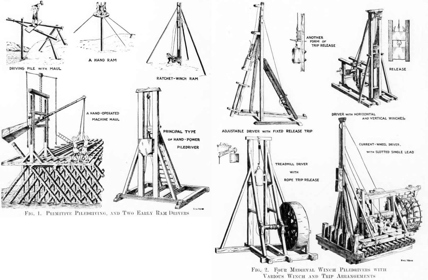
To begin with very primitive methods: Driving with a maul is shown in the small sketch at the upper left corner of Fig. 1. Below is a machine for the same purpose that may be called a hand-operated machine maul; it was adaptable to inclined piles. The problem of driving batter piles was, in fact, of great concern to the old builders, as considerations of stability often demanded such piles. Another primitive device, lacking the idea of a machine, is the one sketched at the top middle in Fig. 1; it is interesting as presenting the ram idea in most simple form. A guide rod or bolt driven into the top of the pile served as guide for the ram, which had a hole in it to slip over this rod.
The three sketches just referred to are from a medieval work on construction. Probably they represent devices which even then were only of historical importance, for the same work sketches the machine piledriving ram at top right in Fig. 1. Here the essential elements of the piledriving machine are present: a pair of leads, a ram moving between them, a hoist rope led over a pulley at the top, and a winch for hoisting. In this case ratchet winch is used, so that one man can lift the rail. It is not apparent how the ram was released; possibly it was released simply by throwing out the ratchet pawl.
The machine of doubtless most extensive use until reatively recent time is the rapid-stroke gang driver show in the lower right corner of Fig. 1, sketched from model in the museum. Here the tail of the hoist rope was fitted with grips for eight or ten men, who by pulling and letting go could give a fairly rapid series of short blows. The base frame of the driver was fitted for inclining the leads by setting back thy rear brace legs in slots of the base as shown.
The application of the winch to piledrivers is shown in various forms in Fig. 2, also sketched from models in the museum. An essential requisite in such machines is a ram trip. Various forms of releasing hook are shown, tripped by hand or by fixed (probably in some cases movable) dogs. The nature of the releasing devices is clearly enough shown by the sketches to require no special reference. It is worth remarking, however, that the scow driver shown at the right at the bottom probably had a clutched winch-drum, instead of a releasing hook. There are cases In which both devices were used, the releasing drum then being probably a time-saving device in returning the rope to pick up the ram after a blow.
We have to thank Dr. Oskar von Miller, Munich, Germany, founder and president of the Museum, for photographs of the models and for the opportunity to make sketches in the museum. These old-time piledrivers make it specially interesting to find, in inspecting German construction work, that steam-hammer piledrivers there are generally worked with manual operation of the steam valve. In different jobs carried out by first-class contracting firms, in both land and scow driving, one man was constantly occupied at the valve rope, giving it a pull for every blow. On inquiry it was explained that this style of steam-hammer driver was used because automatics are not yet in a satisfactorily perfected state.
I don’t know whether the original exhibit survived one or both of the two world wars. As far as the problems with the valve described in the last paragraph are concerned, the following, from The First Pile Hammers, is brought to mind. It discusses the Skinner hammer, a precursor to the Warrington-Vulcan hammers:
The Skinner Hammer was not perfect. Its steam actuated valve was a source of difficulties, a problem that did not end with the Skinner Hammer (Menck hammers also had difficulties with steam or air actuated valves, especially when used with rubber-lined hose where the hose pieces would jam the valve.)
The Germans managed to get past the initial reliability problems of their valves, but when their hammers got to the Gulf others appeared. The mechanically actuated valve of the Vulcan hammer, which had its origins in its steam engines, was a major advantage of the Warrington-Vulcan hammer. This origin is discussed in Some Insight into the Origin of Vulcan’s Pile Hammer Valve System.

