
More Resources
- Foundation Design and Analysis: Deep Foundations, Driven Pile Settlement and Group Capacity
- Design and Construction of Driven Pile Foundations, 2016 Edition, Volume I covers the topics discussed in this post, and does so in more detail, you need to look at this if you’re serious about this topic.
Overview
As a general rule, driven piles are installed in groups. That’s not always the case; offshore monopiles are single piles. It’s also true that, if the spacing is wide enough from pile to pile, group effects don’t apply. In this section we’ll consider axial group effects; lateral ones are different and we will save them when we consider lateral loading.

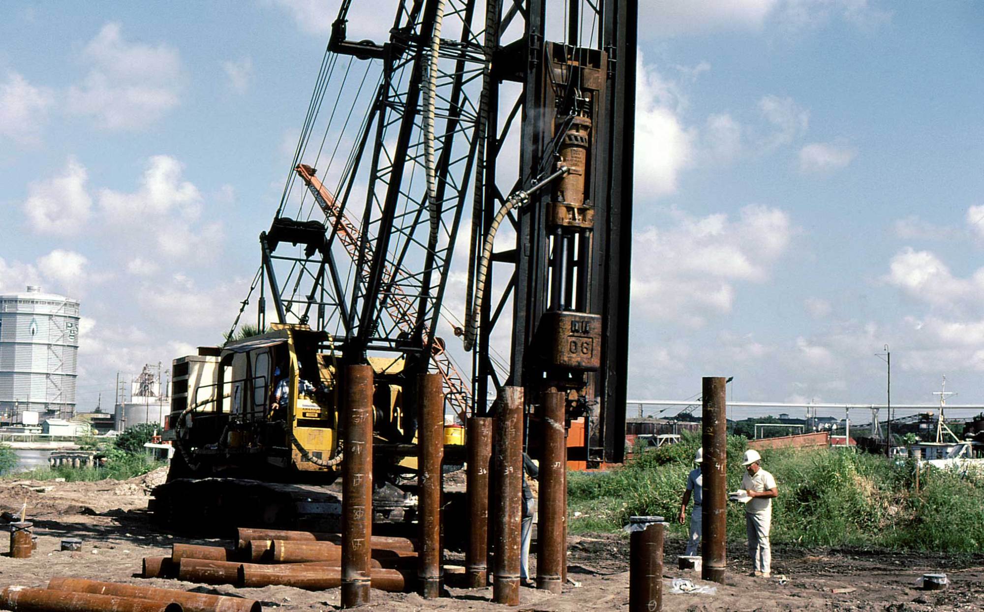
As shown above, pile driven in groups are generally connected together by a pile cap (not to be confused with driving accessories.) The pile cap in turn transmits the load from the structure to the piles. It is either concentric to the centroid of the pile group (which is preferable) or eccentric. This presentation assumes concentric loading; some information on the latter will be given at the end of the presentation.
Stress Zones
One thing that needs to be understood about pile groups is that the way they interact with the soil around them is different than with single piles. The two differences are shown below.

The upper diagram shows the stress “bulb” primarily from the pile toe. For a single pile, the bulb can be rather small. For a group of pile, the bulb can be larger, and more importantly deeper than with a single pile. This means that we have to consider deeper soil strata with pile groups than with single piles.
The lower diagram shows that, as piles are driven, they push soil outward. If the piles are close enough to each other, they can push it into the same places. The formal name for this is “cavity expansion,” and it’s a major advantage of driven piles. As they are driven into the soil, they tend to compact the soil around them simply by the volume of the pile. If the soil in a given spot is being compacted by more than one pile, the results may not be what we would expect with single piles.
Bearing Capacity and Group Efficiency
Leaving out the issue of eccentricity, ideally the bearing capacity (with all of the limitations of that concept) should be the sum of the piles. That’s frequently not the case. We express that with the following equation:

where
group efficiency.
bearing capacity of the group as a whole
number of piles in a group
bearing capacity for a single pile
This assumes concentric loading of the group. With cohesionless soils, we note the following:
- Generally speaking, for cohesionless soils we can assume that
.
- It can be less than that under the following conditions:
- Spacing is too tight. The 2002 AASHTO code allows a minimum centre-to-centre spacing of 2.5 times the pile diameter; an optimum spacing is 3 times the pile diameter.
- There is a weak underlying layer (see Figure 9.31 above.)
- Block failure takes place. We’ll discuss this in more detail with cohesive soils but a common reason for block failure with cohesionless soils is if the piles are more tightly spaced than recommended.
- Jetting or predrilling is used, undermining the cavity expansion.
- It can be more than that if these conditions can be avoided.
For cohesive soils, 
- For pile groups driven in clays with undrained shear strengths of less than 2 ksf (95 kPa) and for the pile cap not in firm contact with the ground, a group efficiency of 0.7 should be used for center to center pile spacings of 3 times the average pile diameter. If the center to center pile spacing is greater than 6 times the average pile diameter, then a group efficiency of 1.0 may be used. Linear interpolation should be used for intermediate center to center pile spacings.
- For pile groups driven in clays with undrained shear strengths less than 2 ksf (95 kPa) and for the pile cap in firm contact with the ground, a group efficiency of 1.0 may be used.
- For pile groups driven in clays with undrained shear strength in excess of 2 ksf (95 kPa), a group efficiency of 1.0 may be used regardless of the pile cap – ground contact.
- Calculate the ultimate pile group capacity against block failure by using the procedure described below.
- Piles in groups should not be installed at center to center spacings less than 3 times the average pile diameter and not less than 3 ft (1 m).
One thing that is more prevelant with cohesive soils than with cohesionless ones is block failure. This is illustrated by the diagram below.

Basically the entire block of piles fail along the plane defined by the dashed lines shown above. The group bearing capacity for cohesive soils can be computed against block failure using the following relationship:

where
embedded length of piles
width of pile group (see above)
length of pile group (see above.) Note that
and
are both measured from the pile centrelines, not the outside edges
weighted average of the uncrained shear strength over the depth of pile embedment for the cohesive soils along the pile group perimeter
average undrained shear strength of the cohesive soils at the base of the pile group to a depth of
below pile toe level

Settlement of Pile Groups
As was the case with bearing capacity, settlement is different with the two types of piles. For cohesionless soils, the settlement is frequently the elastic settlement of the pile, which is discussed in the post on single pile load testing and settlement. Meyerhof’s formula for a group not underlain by a compressible soils using the following formula:

where
settlement of pile group, inches
for silty sand,
for other cohesionless soils
design foundation pressure, the group design load divided by the group area, ksf

The value of 
As a transition to cohesive soils, Design and Construction of Driven Pile Foundations, 2016 Edition recommends the use of Hough’s Method, but doesn’t really show how it is to be used. Hough’s Method has other things to consider, as discussed in the post Closing the Loop (or at least trying to) on Hough’s Settlement Method.
With cohesive soils is is conventional to assume that they act as a shallow foundation at a distance below the surface and the block as a uniform load, as shown below.
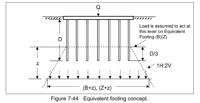
For more complex stratigraphies, the following guidance is typical.


The 2:1 method is explained in the post The 2:1 Method for Estimating Stresses Under Foundations.
Bengt Broms Slides
Below are Bengt Broms’ slides on the subject. Their methodology is a little different and their treatment deals with topics not covered in the previous presentation (like eccentric loading of groups.)


3 thoughts on “Driven Pile Design: Axial Group Bearing Capacity and Settlement”