More Resources
- Foundation Design and Analysis: Deep Foundations, Driven Pile Bearing Capacity
- Design and Construction of Driven Pile Foundations, 2016 Edition, Volume I covers the topics discussed in this post.
Before I get into the actual estimation (and estimation is the operative word here) of axial capacity, I need to make some important observations, as there is a great deal of misunderstanding on the subject, some of which can be fatal at installation or service time.
Bearing Capacity? Perish the Thought!
It is conventional wisdom–and frequently enshrined in the specifications–that for axial loads we are driving a pile to a specific “bearing capacity,” which is a specific load number. The concept is carried over from shallow foundations, where we strive to predict a bearing capacity and thus avoid failure. (The concept really doesn’t work there either, as I note in my post Getting to the Legacy of B.K. Hough and his Settlement Method.)
The problem becomes apparent when you get into static load testing, which we will shortly. For now let us consider the results of a static load test as shown below. The x-axis is the load applied at the head of the pile and the y-axis is the deflection of the pile head at each load step.

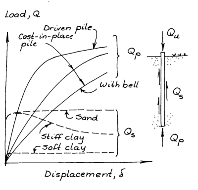
The failure of a deep foundation is progressive, as can be seen at the right. It is very seldom (unless something has gone very wrong somewhere) that pile foundations experience “plunging” (catastrophic) failure, especially if the resistance at the toe is substantial. Put in terms of engineering practice, failure of a deep foundation is most likely to be a service (settlement) failure rather than a strength (bearing capacity) failure. It thus would make sense to design deep foundations based on a settlement criterion. What settlement is acceptable depends upon the application and structure.
This, however, is generally not the way it is done. The “bearing capacity” of a pile (modified by factors of safety or load and resistance factors) has many implied parameters based on experience with the application at hand. While designers will continue to be expected to design to a required capacity, they need to be aware of the limitations of the concept, and in some cases delve into further (settlement) analysis in order to properly design the foundation.
Note: another way of looking at this problem was explored for shallow foundations in my post Lower and Upper Bound Solutions for Bearing Capacity. The problem with this for deep foundations is the following:
- Failure of a deep foundation is (as noted) progressive, starting at the head and going down as the load increases. The point where failure becomes plastic is very early in the process; loads which would be considered conservative do have some plasticity in them.
- The upper bound is a plunging failure, which may be the case but (depending upon who came up with it) just as easily may not.
Capacity, Shaft and Toe, Ultimate and Allowable
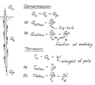
With this caveat out of the way, the bearing capacity of a driven pile can be computed. The essentials of that are shown at the right. The ultimate bearing capacity/resistance of a pile is the sum of the shaft resistance Qs (the resistance along the side of the pile) and the toe resistance Qp (the upward resistance at the toe. The resistance along the shaft is a shear resistance; the resistance at the toe is a compression resistance. In tension the toe resistance disappears and we are only concerned with the shaft resistance and the weight of the pile.
Integral to this discussion is the issue of the factor of safety. We’ll get more into this when discussing ASD and LRFD. Here we can say that there are two values of the “bearing capacity” that we need to determine:
- Qu, the ultimate capacity. This is the capacity of the pile (with all of the conditions discussed earlier) with the pile head fully loaded.
- Qallow, the allowable capacity. This is the capacity of the pile for design purposes, or the capacity in actual use. It is why, as said earlier, piles seldom fail catastrophically; the factor of safety pulls the load back to a region where the settlement is more reasonable. In some cases this may not be enough and a more detailed settlement analysis is required.
Although engineers make a clear distinction between the two, specifications (especially older ones) frequently do not, and it is the job of the designer to figure out which is which. In general, Qallow is what is required for the actual use of the foundation and Qu is what is necessary for drivability (and that being the highest value for a set of piles) and as a key parameter in settlement analyses.
Alpha vs. Beta Methods
The shaft friction Qs of a pile is determined by multiplying the shaft area of the pile by the unit shaft friction, or
(1)
The shaft area for a pile of uniform cross section is generally the perimeter of the pile multiplied by length. In the case where the unit shaft friction
is not constant (which is normally the case) the soil profile is divided into layers and each layer interfacing with the shaft is considered separately.
But how to compute ? For cohesionless soils, this is simply
(2)
where is a constant based on the interaction of the pile and the soil and
is the average effective stress over a layer of soil.
For clays, however, based mostly on Mohr-Coulomb theory, is based on the undrained shear strength, thus
(3)
where is a constant based again on the interaction of the pile and the soil and
is the undrained shear strength of the soil.
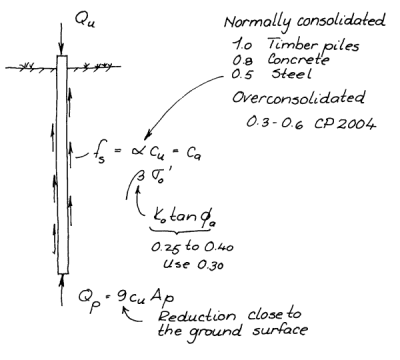
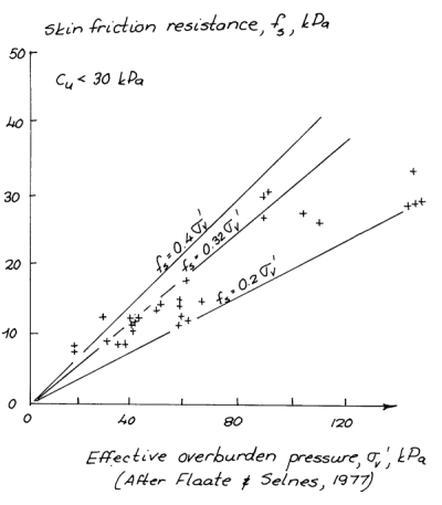
Many methods–and a few of them will be described in a subsequent post–use for cohesive soils and
for cohesionless ones. In the early 1970’s this came under attack, with the idea that Equation (2) can be used for all soils. This has been basically vindicated, if that vindication hasn’t filtered down through the literature. An overview of this topic can be found in the post Shaft Friction for Driven Piles in Clay: Alpha or Beta Methods?
Load Transfer Considerations
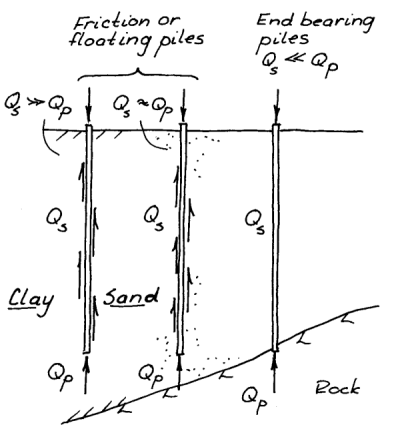
Not all piles transfer the load from the pile head to the soil in the same way. The most important example of this can be seen at the right. Many piles are driven to a “competent” layer of dense sand, stiff clay, or rock of varying degrees of quality, and thus most of the load is transferred to that layer. On the other hand other piles cannot be or are not driven to such a layer, in which case much of the load is transferred along the shaft of the pile.
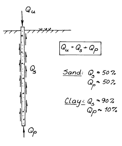
Even with piles which do not extend to a “competent” layer, the load transfer varies depending upon the soil type. As shown at the left, with sands the load can be more evenly split between the shaft and the toe, while with clays shaft resistance predominates. These are generalisations and the results should be verified and quantified during the design process.
Overview of Axial Capacity Estimation Methods
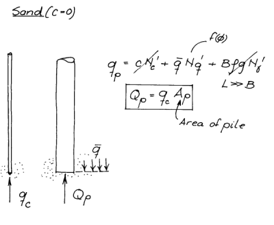
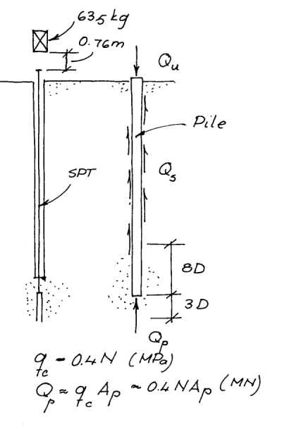
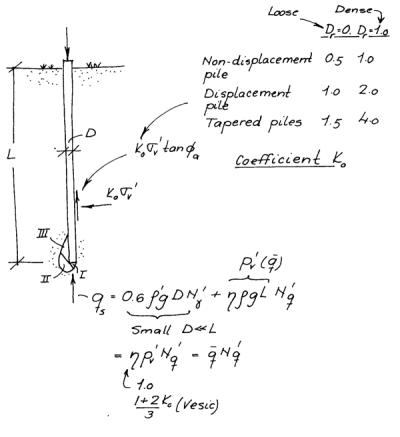
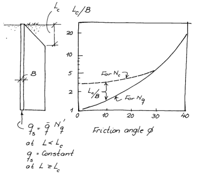
Because of the lack of settlement re the science, there are numerous methods used to estimate the axial capacity of piles. Below is a little “slide show” where several of these are explained.









5 thoughts on “Driven Pile Design: Axial Loads, General Considerations”