
For the rest of the book click here.
Recently, some construction organizations have begun to use the vibration method for immersing and removing large-diameter casing pipes.
At Stalingradgidrostroy recently [65], a hydrovibration method for immersing pipes with a diameter of 400-500 mm has been developed and successfully implemented. Using this method, it was possible to drill water-draining wells up to 46 m deep in sandy soils with layers of loam and clay up to 3-4 m thick. For these purposes, an E-1003 crane with a boom 20-23 m long and a VPP-2 vibratory hammer were used with simultaneous jetting, the so-called hydraulic drill. The washing was carried out using a powerful pump with a water flow rate of up to 100 m3/hour at a pressure of up to 20 atmospheres.
Wells up to 15 m deep were passed through one column of pipes with a diameter of 400-500 mm. At a depth of up to 25 m, two columns with diameters of 500 and 400 or 600 and 500 mm were used, and at greater depths, three diameters of 700-500-400 mm, and sometimes four of 700-600-500-400 mm. The hydraulic drill was a nozzle with one nozzle with a diameter of 28-30 mm, providing, like a hydraulic monitor, a powerful concentrated jet.
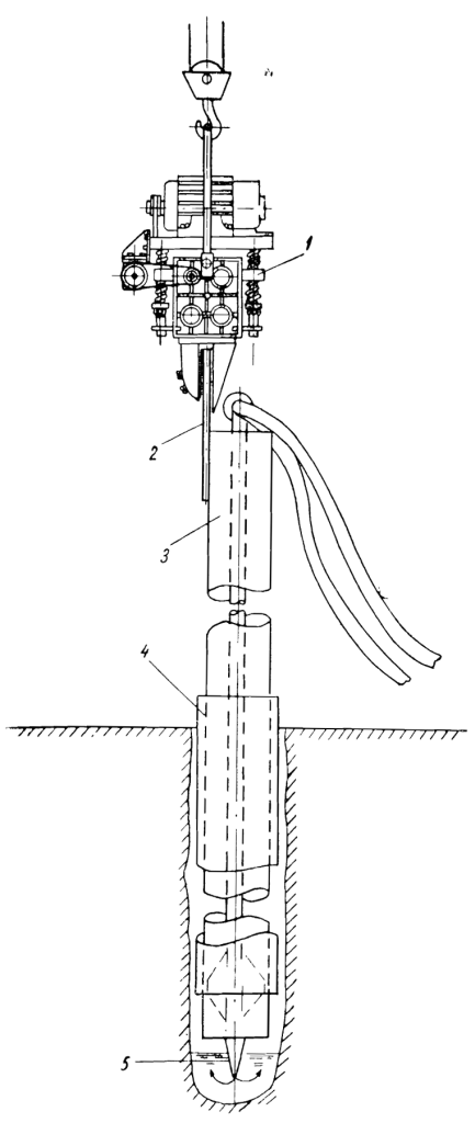
Wells were drilled as follows. A section of sheet pile was welded to the first casing guide pipe (Fig. 110), to which a vibratory driver was attached. A pipe with a diameter of 100 mm with a nozzle at one end and a tee at the other end was inserted into the casing. Two high-pressure hoses with a diameter of 75 mm were connected to the tee, through which water was supplied from the pump to the nozzle. The total length of the inner pipe with the nozzle was usually 0.1-0.2 m longer than the length of the immersed pipe.
A pipe prepared in this way with a washing device was installed by a crane at the drilling site, the pump was turned on, then the vibratory driver, after which the pipe was quickly immersed in the ground, and the sand from its internal cavity was washed out with water. When the pipe was immersed to its full length, the mechanisms were turned on, the vibratory driver was removed from the pipe and the hydraulic drill was removed.
First, the lower part of the second column was inserted into the pipe guide column, and then the lower part of the hydraulic drill. After this, the crane lifted the upper part of the second pipe column with a vibrating hammer attached to it and a hydraulic drill pipe inserted inside. Both parts of the hydraulic drill were connected by flanges, and the upper and lower parts of the second pipe column were welded.
The immersion of the second column, and, if necessary, the third and fourth, was carried out in the same way as the first.
After equipment and installation of gravel filters, the casing pipes were removed using the same vibratory driver.
The hydrovibration method, compared to the rope-impact method, allows you to increase the speed of drilling deep wells by at least 2-3 times, and small ones by 5-6 times; The cost of 1 m of hydrovibration drilling is on average four times lower than that of cable-percussion drilling. In the Leningrad construction department of the Gidrospetsfundamentstroy trust, when drilling artesian wells, vibratory drivers VPP-2 and VPP-4 [20] are used to lower and retrieve casing pipes; deepening the latter and excavating soil are carried out in the usual ways.
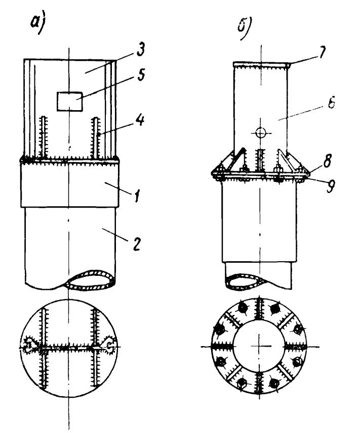
Adapters are used to connect vibratory plungers to casing pipes (Fig. 111). Used in combination with the head of the VPP-2 vibratory driver for metal sheet piles (Fig. 111a), the adapter consists of a coupling 1, screwed onto the upper end of the immersed or retrieved casing pipe 2. A plug is welded to the coupling, to which a section 3 of a flat profile sheet pile is welded , reinforced with gussets 4. A window 5 is cut out in the tongue-and-groove wall to capture the adapter with the wedge of the tongue-and-groove head.
An adapter of a different design (Fig. 111b) is a section of steel pipe 6 with a diameter of 290 mm; a plug 7 and a flange 8 are welded to its upper and lower ends, with which the pipe section is connected to the flange 9 of the driving head 10, which is screwed onto the casing pipe.
Drilling wells using vibratory hammers is carried out from a drilling rig or from a Uralets rig.
During the process of drilling an artesian well with a depth of 165 m on the site of an industrial facility in the Stalingrad region, immersion of casing pipes when drilling silty sands was extremely difficult due to the pinching of pipes in the ground and the formation of plugs up to 15 m high. As a result, during the shift the drilling rig was able to plant the column casing pipes by no more than 0.75 m.
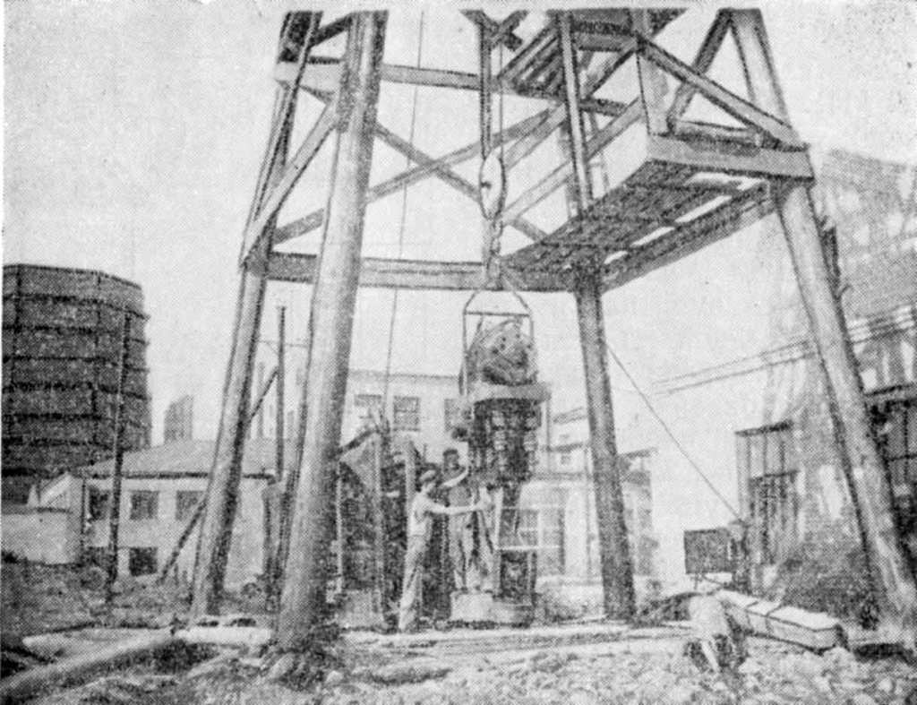
The use of the VPP-2 vibratory driver made it possible to dramatically increase labor productivity. When the vibratory driver was turned on for a short time (on average for 2-3 minutes) connected to the submersible casing pipe, the latter was lowered to a depth of 0.7 m, and during a shift it was possible to pass 4-5 m of the well, which is five to six times the speed achieved with conventional drilling. The well was brought to the design level, obtaining the required water flow almost a month ahead of schedule.
A general view of the drilling rig at the time of planting casing pipes with a vibrating hammer is shown in Fig. 112.
In the Kalach area on the Don, it was impossible to remove pipes from one of the artesian wells using conventional methods. Using a vibratory hammer, this work was completed in one shift. The pipe string was removed using a 3-ton manual winch and a pulley system, which made it possible to increase the traction force to 12 m. Traction pulleys were connected to the casing head directly through compression brackets (without a shock absorber).
The casing pipes are removed in the following sequence: to preliminary break the connection between the pipe and the soil, the vibrating hammer was turned on for 2-3 minutes. without rope tension. It was then turned off and reactivated once the full traction force had been applied to the pipe string, allowing the pipe string to rise quickly.
A well 50 m deep, drilled in quicksand in the same area, could not be brought to the design mark for almost two months in the usual way, that is, by driving pipes with an overhead mechanical hammer. Repeated extraction of soil with a bailer gave a negative result: gaps formed around the pipes, threatening to collapse the tower. The use of a VPP-2 vibratory hammer for planting pipes made it possible to complete the drilling in four hours.
In the same area, over two years, about 40 wells of varying depths were drilled using vibratory hammers. The speed of drilling wells and removing casing pipes has increased by more than 10 times compared to drilling with conventional methods, and the cost of work has been reduced by approximately half.
At the Mospodzemgaz trust, using a V-108 vibratory driver, pipes with a diameter of 150-220 mm were removed, buried in the ground to a depth of 45-60 m and partially cemented in the annulus. Of the 35 wells where a vibrating hammer was used, in twelve cases the pipes were completely removed, in twelve they ruptured at a depth of 25-55 m, and the rest could not be removed.
The examples given show that the use of vibratory pile drivers when drilling deep wells and removing casing pipes in many cases gave the desired effect, although vibratory pile drivers were used that were not suitable for this work.
The first attempt to create special vibration machines for extracting casing pipes with a diameter of up to 250 mm took place in the Leningrad branch of Gidroenergoproekt. Here, under the leadership of A.E. Leitgold, a vibratory driver with a through hole and two sprung electric motors was developed, manufactured and tested. The vibrator can be attached to the casing pipe anywhere. In this machine, in addition to the spring system that suspends the electric motors, there is a special spring shock absorber with a large load capacity, which is activated when extracting casing pipes when the extraction force exceeds a certain limit.
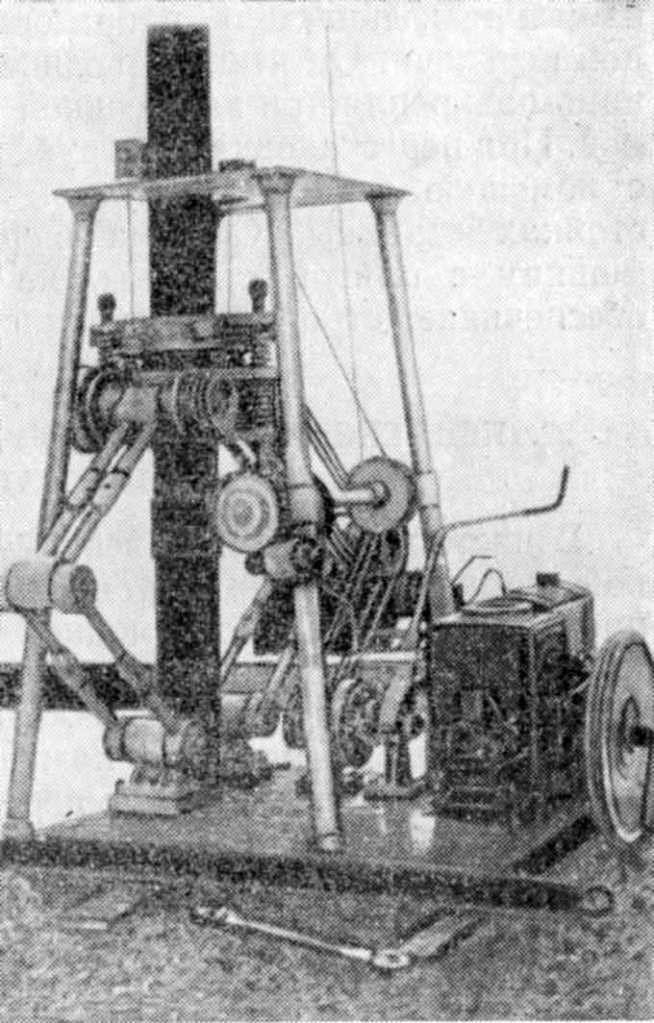
Another design of a vibratory driver for casing pipes (Fig. 113) with an internal combustion engine was proposed by V.Z. Sukhanov, L.D. Akimova, M.M. Andreev, S.A. Volkov and I.A. Trusov.* The vibratory driver is a machine consisting of a frame, a motor, a vibrator and a two-stage V-belt drive. It has a through hole and is secured to the casing pipe with a ring cap using screw clamps. When rearranging the pipe, lifting or lowering is carried out using a small hand winch attached to two stands of the frame. A system of articulated arms connecting the machine to the bed plate on which the engine is installed ensures its strictly directed movement.
*Authors certificate No. 103929 with priority dated February 12, 1955.


One thought on “Drilling Using Vibration of Deep Dewatering and Artesian Wells”