
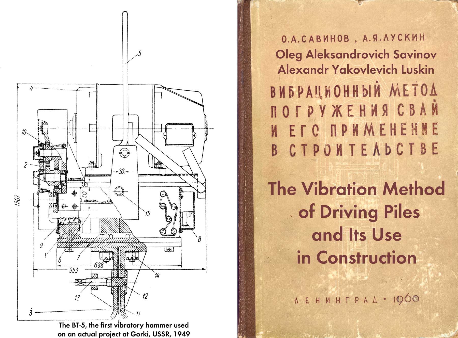
The rest of the book is here. Both of these topics would also occupy Vulcan and the construction industry. In the late 1950’s and early 1960’s Vulcan would develop its Sand-Drain hammers, but as you can see the Soviets were already doing this installation using vibratory drivers. (For an overview of sand drains and Vulcan’s efforts, see Vertical Drains: Sand and Wick.) The use of vibratory drivers for drilled shaft casings didn’t really get going in the U.S. until the 1970’s, and Vulcan vibratory drivers were involved in that work as well.
To install cast-in-place concrete piles, as well as sand piles-drains, a standard pipe-shell is immersed in the ground, closed from below with a loose shoe. The shell is filled with concrete or sand and removed, and the pipe filler along with the shoe remains in the ground.
Until recently, bulky and low-performance steam pile drivers equipped with single-acting hammers were used to drive and remove standard pipes.
Powerful vibratory pile drivers allow this work to be done much faster, while at the same time ensuring good compaction of the aggregate during the process of vibrating the pipe.
It is recommended to carry out work on the installation of concrete cast-in-place piles and vertical sand piles-drains with vibratory loaders of types V-102, V-104, V-108, VPP-1 and VPP-2 in combination with jib cranes E-505, E-1003 on a crawler, etc. The possibility and feasibility of using pile pile drivers for these purposes in each specific case is established based on local conditions, and it should be taken into account that the productivity of pile driver installations is usually lower than that of crane ones.
Vibratory hammers of the simplest types V-102, V-104 and V-108 must be equipped with special shock absorbers that isolate the crane boom from vibrations when removing the standard pipe.
In cases where work is being carried out where the upper layers of the site are represented by relatively weak soils, the immersion of the standard pipe can be carried out without guide devices mounted on a crane. The lifting capacity of the crane must be sufficient to ensure removal of the pipe after filling it with concrete or sand. The vertical position of the pipe during the immersion process is achieved, as when immersing sheet piles and piles, by limiting the speed of translational movement of the pipe into the ground.
If the crane’s lifting capacity is insufficient, as well as if there are upper layers on the site composed of relatively dense soils, it is recommended to use jib cranes equipped with guide posts or pile driver booms.
With a standard pipe length of up to 8 m, one design of the guide post is used (Fig. 106a), and with a length of up to 16 m, another design is used (Fig. 106b). Regardless of the design and length, being attached to the boom and supported on the ground, the stand helps to obtain a significantly greater lifting force on the crane hook without loss of stability and ensures a vertical position of the pipe when immersed. The vibratory driver and the stand are connected by a sliding bracket, which allows the vibratory driver with the standard pipe to move freely along the stand only up and down.

a) guide post designed by V. T. Sukharev for an standard pipe up to 8 m long; b) rack guide for pipes up to 16 m long, 1 – standard steel pipe; 2 – vibrating driver; 3 – guide post
When using vibratory hammers to install cast-in-place piles and drains, standard pipes with an outer diameter of 325-377 mm can be used. Driving pipes of larger diameter using vibratory hammers is carried out only in soft soils.
It should be noted that cast-in-place piles and sand piles-drains with a diameter of less than 400 mm do not always satisfy the requirements for them. Thus, based on calculations and existing experience, Yu. M. Abelev [1] comes to the conclusion that it is necessary to use pipes with a diameter of 400-500 mm for the construction of sand piles. To immerse such pipes to a significant depth, vibration units must be created on the basis of jib cranes, operating on the principle of vibration indentation, using for this purpose the weight of the pile driver boom with which the cranes are equipped.
Used for the installation of cast-in-place concrete piles reinforced with a lightweight frame, the standard pipe at the top is adapted for quick connection and release of the vibratory driver. The simplest is a flange connection using three or four bolts with a diameter of 36 mm. It is more convenient when the bolts are secured to the upper flange, which is included in the welded assembly that replaces the head cap. The unit, consisting of a plate, a piece of pipe 200-300 mm long and a flange, is secured to the bottom of the vibratory driver with bolts that are usually used to secure a pile or tongue-and-groove head.
The pipe is made blind along its entire length, with the exception of two holes with a diameter of 30-40 mm, located at a distance of 100-150 mm from the top of the pipe. A kingpin is placed in the holes. While the pile is being concreted, a reinforcement cage is suspended from the pin. There is no need for a pivot in cases where the pile is not reinforced at all or is reinforced along its entire length.
The lower end of the standard pipe is closed with a loose shoe or equipped with a standard drop-down tip.
Lost shoes are made of cast iron, wood or reinforced concrete. They are a cone, the diameter of the base of which is 20-30 mm larger than the outer diameter of the pipe. At the base, the cone has a cylindrical part 100 mm long of such a diameter that it fits freely into the pipe. Cast iron and reinforced concrete slip shoes can be made hollow.
When making cast-in-place concrete piles, the lost shoes are rigidly fastened to the standard pipe during immersion. The fastening is done in such a way that after immersion the shoes are easily released from the pipe, remaining at the base of the pile along with the concrete.
There are several ways to fasten loose shoes with a standard pipe using one or two rods, fixed at one end to the shoe using hooks hooked onto the rods inside the shoes, and at the other end to the upper flange using nuts screwed onto the threads at the end of the rods.
It should be noted that the use of ties for fastening loose shoes is advisable in cases where work is carried out without guideposts and the standard pipe can be laid on the ground after the manufacture of each pile.
The second method of attaching lost shoes to a standard pipe, proposed by A. M. Rukavtsov, is to weld them at several points. To do this, they must have steel outlets at the base, firmly embedded in the body of the shoe. When casting cast iron shoes, steel plates can be placed; Several reinforcing bars protrude from the body of the reinforced concrete shoes.
Using this method, you can also use wooden loose shoes with a steel frame for the base of the cone, attached with crutches.
The release of loose shoes, welded to pipe by electric welding, is carried out using a tubular rod, 20-30 cm longer than the standard pipe.

1- stop for the ring; 2 – connecting ring (lost); 3 – shoe petal; 4 – hinge; 5- cable; 6 – strips; 7 – bolts; 8 – bracket
The drop-down standard shoe designed by T. F. Rybin (Fig. 107) consists of four petals hinged to a pipe, which are held in a closed position by a ring during immersion and filling of concrete. When the pipe is removed, the ring slides off the end of the shoe, the petals open and the pile filling material fills the resulting hole in the ground as the pipe is removed.
The length of the standard pipe for constructing concrete piles is determined so that its internal volume corresponds to the volume of concrete, taking into account the compaction of it and the soil.
The process of manufacturing a cast-in-place concrete (reinforced) pile consists of several operations: fastening the loose shoe to the standard pipe and installing them at the immersion site; immersing the standard pipe; detachment of the vibratory driver; releasing the pipe from the shoe; installing a reinforcement cage into the pipe and temporarily fastening it to the pipe; pipe filling; releasing the fittings from the pipe; connecting the vibrating hammer to the pipe; removing the standard pipe and washing it with water.
In cases where a pipe with a drop-down shoe is used to install vibrated piles, the entire work process remains basically the same, the only thing that arises is the need to close the shoe flaps and put on the ring when installing the pipe at the immersion site.
If for the installation of cast-in-place piles, loose shoes are used, fastened to the pipe using ties, they are released as follows. After the pipe is immersed to the required depth, the nuts of the tie rods are released and unscrewed from the thread. Then the flange connection of the pipe with the vibrating hammer is deployed and the latter is lifted up 1-1.5 m above the end of the pipe, after which the strands are removed from the pipe.
When electric welding loose shoes are used (when working with guideposts), the shoe is released after the flanges are separated. For this purpose, a rod is used – a pipe with a diameter of 150-200 mm. In the upper part it has a flange, the size and location of the holes coinciding with the lower flange of the head of the vibratory driver, and in the lower part – a welded round steel blank with a diameter of 20-30 mm less than the internal diameter of the standard
After unscrewing the bolts of the flange connection, the device for knocking out the shoe is attached to the head with a short sling, lifted together with the vibratory driver, inserted into the submersible pipe and installed on the shoe. Then the flange of the tubular rod is fastened to the flange of the vibratory hammer and the latter is turned on for a few seconds. At the same time, the vibratory driver with the rod begins to bounce on the shoe and quickly knocks it out of the casing. After this, the rod is freed from the vibrating loader and, using the same short sling, is removed from the pipe and laid on the ground, for which the lower end of the rod is pulled away from the guidepost as the vibrating loader is lowered.
The process of installing reinforcement when installing vibrated concrete piles requires some explanation.
In cases where the pile is reinforced over its entire length, the prepared frame is secured with a sling to the head of the vibratory driver, lifted up, inserted into the pipe and installed on the shoe freed from the pipe. Most often, cast-in-place piles are reinforced only in the upper part by ½ or ⅓ of their length. With such a length of the reinforcement cage, appropriate measures must be taken to ensure its correct position, preventing the frame from “sinking” in the concrete when removing the standard pipe by vibration.
To do this, the reinforcement cage must be made with two elongated rods, with which it rests on the shoe and is held at the required height, or a short frame must be suspended from the top of the pipe.
This is done in the following order: rods made of steel rods are attached to the reinforcement frame, the length of which is determined in such a way that when suspended on a pin in the upper part of the immersed pipe, the frame takes the position corresponding to the project. A sling is attached to the free ends of the cords equipped with hooks, with the help of which the frame is suspended from the vibratory loader. After this, the vibratory loader with a frame is raised to the required height and the frame is subsequently lowered into the pipe. At the moment when the upper ends of the tie coincide with the holes in the pipe, the descent stops, the pin is inserted into the holes of the pipe and the tie is suspended on the pin, after which the sling is removed.
After the reinforcement is fixed to the pipe, it is filled with concrete.
For concreting the pile, it is recommended to use a funnel made of sheet steel. Installation of the funnel and lifting of buckets of concrete is carried out in the same way as the reinforcement cage, using a sling attached to the head of the vibratory loader.
Before starting to remove the pipe filled with concrete and sand for loading, the reinforcement cage is disconnected from the pipe. To do this, a pin is knocked out, on which the strands of the reinforcing frame are suspended. Instead, a steel disk with a diameter of 10-15 mm less than the internal diameter of the pipe, is brought under the hooks of the ties and placed on the surface of concrete or sand. The disk should have cutouts into which the cords and a handle fit, making installation and lifting easier.
A vibrating hammer is attached to the pipe and its extraction begins. In order for concrete to be better compacted under the influence of vibrations, the extraction speed should not exceed 2-3 m/min. It is recommended that after raising the pipe by 0.5 m, stop for 10-20 seconds. and then practice these stops every meter. In case of weak water-saturated soils, in order to avoid thinning and ruptures in the body of the pile, after each stop it can be recommended to immerse the pipe by 10-15 cm. Such alternating steps, although they will slow down the pace of work, provide good quality of compaction of the concrete of vibrated piles.
If a standard pipe equipped with a drop-down tip during removal is used to install vibrated concrete piles, re-immersion after filling is not allowed, since the shoe petals may be damaged.
To ensure the required quality of vibrated concrete piles, it is necessary to carefully monitor the implementation of all operations, ensure that there is no water and soil inside the standard pipe, check the volume of concrete, etc. All the main data of the pile manufacturing process must be noted in the log.
The first experience in using the vibration method for installing cast-in-place concrete piles was carried out by D. D. Barkan together with specialists from the Riga Construction Trust No. 21.
A total of five experimental piles were manufactured. Four of them were subjected to static testing using hydraulic jacks. Data characterizing the experimental piles and their load-bearing capacity are given in Table. 47.
| Pile Number | Pipe diameter in mm | Immersion depth in m | Immersion time in min. | Critical load in tons |
| 1 | 325 | 7.5 | 7.3 | 18 |
| 2 | 275 | 8.0 | 6.5 | – |
| 3 | 325 | 9.3 | – | 35 |
| 4 | 275 | 10.0 | 7.0 | 46 |
| 5 | 275 | 8.0 | 6.0 | 30 |
The relatively low critical load on pile No. 1 is explained by the fact that, due to insufficient tightness of closing the pipe with a shoe, groundwater got into it, which, during concreting, overflowed abundantly over the edge of the loading hole and washed out the cement from the concrete. For this reason, the value of the critical load obtained during testing apparently relates not to the settlement of the pile, but to its destruction.
Load bearing capacity of piles No. 3 and No. 4 turned out to be satisfactory. With the values of loads on the piles indicated in the table, their settlements did not exceed 10 mm. Pile No. 5 had a significantly lower load-bearing capacity due to the fact that its penetration into the ground turned out to be 1.3-2 m less.
The experiments carried out revealed the technical and economic feasibility of using the vibration method for constructing bored piles and at the same time indicated the need to use more advanced and powerful vibratory drivers, as well as better tips for the standard pipe.
On a much larger scale, these experiments were carried out at one of the facilities of the Leningrad Construction Department of the Sevzapmorgidrostroy trust.
When constructing an industrial building, it was planned to drive reinforced concrete piles under strip foundations, which were replaced by vibrated concrete piles with light reinforcement along the entire length. During the work, the technology for installing bored piles was developed. A new method for constructing bored concrete piles with a widened pear-shaped heel proposed by A. M. Rukavtsov was also tested.*
*Author’s certificate No. 117650 with priority dated February 18, 1958.
The soils of the construction site are water-saturated fine-grained sands and sandy loams, at a depth of about 5 m, underlain by a thick layer of heavy ribbon loams. The groundwater horizon level is at a depth of about 1.5 m.
The new project provided for the installation of cast-in-place piles 8.5 m long, buried in the ground 9.3 m from the surface.
The calculated load on one pile was 21 tons. To immerse and remove the standard pipe, a VPP-2 vibratory loader and an E-505 crawler crane equipped with a 12 m long boom were used. No additional guideposts were used.
For the manufacture of vibrated piles, standard pipes with an outer diameter of 377 mm, a wall thickness of 10 mm and a length of 9-9.5 m were used. In the initial period, a pipe was used, equipped at the lower end with a drop-down shoe, and a steel sheet reinforced with gussets was welded to its upper end. The sheet had a rectangular hole for the wedge of the tongue-and-groove head of the VPP-2 vibratory loader, and in the upper part of the pipe there was a loading hole for concrete.
A reinforcement cage was placed into a pipe lying on the ground surface in a horizontal position through an open shoe; the shoe was closed and a loose ring was put on its tip, which was tied with wire during the ascent. Then the vibrator along with the pipe was lifted by a crane and installed at the immersion site. After the loose ring was freed from the wire, the vibrating driver was turned on, and the crane operator began a smooth descent, so that the vibrating driver with the pipe was in a suspended state. After immersion to the designed depth, the pipe was filled with concrete and then removed.
Control measurements of the lot after the pipe was immersed showed that due to insufficient tightness of the opening shoe, water and liquefied soil penetrated inside. This was facilitated by the relatively long immersion time of the pipe to a depth of 9 m – 10-15 minutes, which was apparently determined by the insufficient value of the specific immersion pressure.
To increase the tightness of the shoe, the lost ring was replaced with a welded conical cup. Two steel strips were welded to two opposite flaps of the shoe so that they would close the cracks along the entire length – from the pipe to the top of the conical lost cup. And these measures did not prevent groundwater from entering the pipe.
During static tests of three piles, critical loads of 20, 40 and 45 tons were obtained, and for the second and third piles, the settlements at a load of 20 tons were less than 5 mm, which fully satisfied the requirements for the load-bearing capacity of the piles. However, in order to completely eliminate the entry of water into the pipe and obtain a higher load-bearing capacity, a method of constructing vibrated piles was used using loose reinforced concrete shoes welded at several points to the pipe by electric welding.
For this purpose, a new pipe was made, consisting of two parts; the main one was 9 m long and had a flange at one end; the rest was short, 0.7 in length, and on one side had the same flange, with the help of which both parts of the pipe were connected to each other. The other end of this part of the pipe was rigidly connected to the vibrating hammer.
In addition to this main pipe, a rod was made from a pipe with a diameter of 219 mm, which had a blank with a diameter of 320 mm at one end, and a flange at the other end with which the rod could be attached to the vibratory hammer. The length of the rod from the bottom edge of the blank to the flange was 9.3 m.
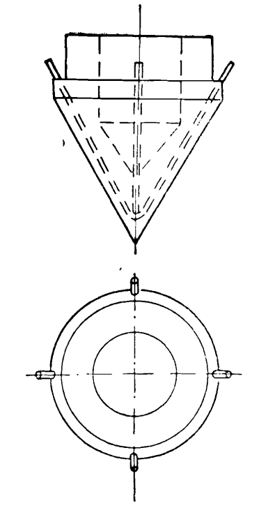
Lost reinforced concrete shoes (Fig. 108) were a reinforced plug that fit freely into the pipe, with a conical tip. Where the end of the pipe adjoined the shoe there were four reinforcing bars protruding from the concrete.
The sealing of the seam between the pipe and the shoe made of tarred hemp rope completely prevented water from entering the pipe when it was immersed.
The need to forcefully knock out the shoe from the pipe gave rise to the idea of constructing vibrating piles with a pear-shaped widening, similar to those obtained in Franki piles using the impact method. This idea was tested at the specified facility.
After the pipe was immersed and the vibrating hammer was released, before knocking out the shoe, a little concrete was recorded into the pipe, the layer thickness of which was 70-80 cm. Then a rod was inserted into the pipe, which was attached to the vibrating hammer, and compaction began. Under the influence of the impact of the rod, the shoe was knocked out of the pipe and, together with the concrete, began to sink into the ground. Coming out of the pipe, the concrete was pressed into the side walls of the well and formed a widening. After lowering by 20-30 cm, the rod was raised, concrete was added to the pipe and the tamping operation was repeated. At the same time, make sure that a concrete plug of at least 10-20 cm in height remains in the pipe.
Thus, about 0.5 m3 of concrete was easily compacted into the heel. Then, a reinforcement cage was installed on the widened heel formed in this way, the pipe was filled with concrete in the required volume and removed with stops without turning off the vibratory hammer.
As a result of static tests, it was found that the critical resistance of vibrated piles with a widened heel is 2-2.5 times greater than the resistance of piles without widening.
The considered method of constructing vibrating piles is effective and economical. Preliminary calculations show that their cost, related to the bearing capacity, is 4-5 times less than for conventional driven piles.
The process of installing sand piles and drains using vibratory hammers is much simpler and consists mainly of immersing the pipe, filling it with sand and removing it. To make sand piles, in all cases you can use a standard pipe equipped with a drop-down tip. The tightness of the latter does not matter at all, since the entry of groundwater into the pipe does not harm the quality of the work. Moreover, to better compact the sand, after filling it, it is recommended to fill the pipe with water until it is completely saturated. The upper end of the pipe is fixed to the vibrating hammer for the entire duration of work, and sand is filled through the loading hole.
The length of the pipe is taken to be 1.5-2 m greater than the design depth of the drain piles so that the entire volume of loose sand fits into it, which is compacted when the pipe is removed with vibration in the resulting well. The corresponding volume of sand is compacted in each specific case experimentally .
To date, considerable experience has been accumulated in constructing sand vibratory piles and drains. Riga Construction Trust No. 21, in creative collaboration with the Research Institute of Foundations, work was carried out at several industrial and civil construction sites to compact weak water-saturated foundation soils with sand piles-drains [53].
For these purposes, B-102 vibratory hammers, equipped with a special shock absorber, were used in combination with a crane equipped with a guide post (Fig. 109).

Although sand was poured into the pipe manually, the overall productivity of the installation was very high and reached 50 piles per shift. With this installation, using a standard pipe with a diameter of 325 mm, about 33 thousand sand drain piles were made to a depth of 6-7 m.
It should be noted that the degree of soil compaction by installing sand piles and drains turns out to be relatively small.


One thought on “Construction of concrete cast-in-place piles and sand piles-drains using the vibration method”