
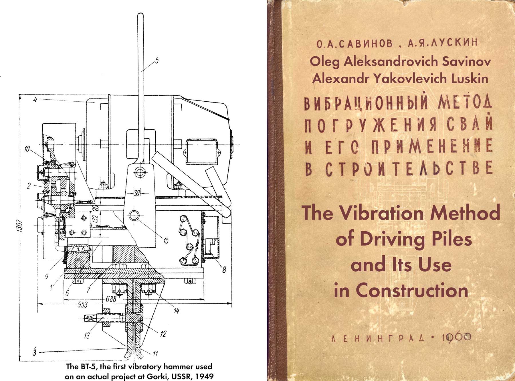
For the rest of the book, click here. Driving concrete piles by vibration is still not as accepted as it should be, but doing it has preoccupied researchers both geotechnical and equipment application since the early days of the technology. The Soviet approach to it was to use low speed, high eccentric-moment vibrators, a practice the Japanese adopted but which has been superseded in later application. A more modern treatment of this topic in a Soviet context can be found in Driving Prismatic Steel Reinforced Concrete Piles and Driving Cylinder Piles.
Currently, low-frequency vibratory drivers VP-1 and VP-3 of longitudinal action are used for vibration driving of heavy solid-section piles weighing over 2 tons or hollow ones.
The VP-1 vibratory driver is used when it is necessary to ensure the load-bearing capacity of a pile corresponding to a critical load not exceeding 100 tons. For a critical load in the range of 100-200 tons, they resort to the VP-30 vibratory driver. There is also a method developed by the Bridge Research Institute [2] for selecting the required type of machine , which makes it possible to determine which of the vibratory drivers, based on the main parameter – the static moment of the eccentrics – is most suitable for driving a pile, depending on its size and weight, as well as on the soil lying on the site.
The highest rates of speed and depth of immersion, and therefore productivity, are achieved when vibrating heavy piles into weak, water-saturated soils.
Satisfactory results are obtained when diving in medium-density soils. If there are low-moisture and dense soils at the base of the structure, low-frequency vibratory drivers of longitudinal action turn out to be ineffective.
Approximate characteristics of reinforced concrete piles of continuous cross-section, driven into medium-density soils with a vibratory driver VP-1, VP-2 and VP-3, according to tests conducted by the Bridge Research Institute and Glavmostostroy in 1954-1955. on a site composed of sandy soil is given in Table 38.
| Indicators | Model of Vibratory Hammers | ||
| VP-3 | VP-1 | VP-2 | |
| Section of Reinforced Concrete, cm | 40 x 40 | 35 x 35 | 30 x 30 |
| Maximum immersion of piles, m | 9-10 | 7-8 | 4-5 |
| Immersion time, minutes | 12-15 | 12-15 | 15-20 |
| Maximum critical load on pile, tons | 200 | 100 | 50 |
The experience of using low-frequency vibratory hammers in soft soils (water-saturated fine-grained sands, ribbon clays, etc.,) characteristic of Leningrad, shows that the maximum dimensions of piles driven by these machines can be significantly larger. So, for example, when using the VP-1 vibratory driver, the maximum immersion depth of piles of 40 x 40 cm, which took 20-25 minutes, reached 16 m. With the VP-3 vibratory driver, piles can be driven into soft soils to an even greater depth.
The high efficiency of using vibratory drivers for driving heavy piles into soft soils has been established for a long time. Over the past years, much has been done to improve the technology of piling operations using vibratory hammers.
Currently, it may be recommended to drive piles using low-frequency vibratory hammers using the following equipment and devices: universal pile drivers; self-propelled cranes with suspended booms; self-propelled cranes and special guide frames.
A distinctive feature of the process of driving heavy piles using low-frequency machines is the need for separate lifting of the pile and the vibratory driver.
When using a pile driver or a crane with an overhead boom, the pile and vibratory driver are lifted using separate cables. First, the vibratory driver is usually lifted, then the pile is lifted with a pile cable, holding it until it is fastened to the vibratory driver. During the immersion process, the latter is held with the pile in a vertical or inclined position by the arms of a pile driver or crane, along which the guide rollers of the machine move.
If the crane does not have guide arms to hold the piles in the required position and ensure the correct direction at the beginning of driving, they resort to collapsible frames and other guide devices capable of performing this function. Grillage conductors are sometimes used for these purposes. In some cases, the installation of leader holes can be recommended in the ground, to a depth of 1.5-2.5 m of such dimensions that they ensure the correct position of the pile when immersed.
Depending on local conditions and the availability of equipment, we can recommend a technique in which the movement of the vibratory driver is ensured by a pile driver, and the feeding, lifting and holding of the pile until it is fastened to the vibratory driver by a self-propelled jib crane. With such an organization of work in appropriate conditions, high levels of labor productivity can be achieved.
Of all the currently used devices for fastening piles with a vibrating hammer, the most advanced is the cap proposed by K. G. Protasov and B. P. Tatarnikov.*
*Copyright certificate No. 94969 with priority dated May 9, 1951.
The cap (Fig. 95) is a conical self-jamming device consisting of a receptacle 1 with a conical socket connected to the bottom of the vibrator 2, a conical pin 3, which is rigidly attached to the pile 5 using a plate 4. Figure 95 shows an option for fastening a conical pin in a reinforced concrete pile using reinforcing bars protruding from the concrete with threads and nuts. This device has a drawback: during transportation, the protruding ends of the reinforcement are often deformed or the screw thread becomes clogged; straightening the ends of the reinforcement can lead to concrete spalling.

Another, more successful way of attaching a cone to a reinforced concrete pile is shown in Fig. 96.
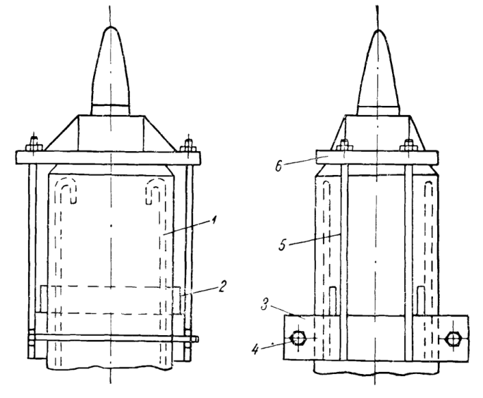
During the manufacturing process of the pile, two steel strips 2 are welded to the reinforcement 1 of such length that after concreting they protrude from the body of the pile by 20-25 mm. A clamp 3 rests against the protrusions, tightened on the pile with bolts 4. Long bolts 5 are welded to the clamp, with the help of which the base plate of the cone 6 is attracted to the head of the pile.
If conventional piles without devices for securing the cone are used for vibration driving, the following fastening method is recommended. At a distance of 400-500 mm from the end of the pile, the reinforcement is exposed on both sides, strips are welded to it, into which the clamp rests.
There is another way to attach the cone to the pile [52]. With this method (Figure 97,) the cone is tightly welded to the cap, which is a rectangular box 1 with dimensions 15 mm larger than the cross-section of the pile. A base plate of 2 cones is welded to the top of the box. An oak spacer 3 with a height of 200 mm is tightly placed inside the box. A strip 4 is welded to one of the sides. On the opposite side there is a cutout into which the second strip 5 fits freely. The cap is secured to the pile using strips and bolts.

The considered pile cap device can be successfully used for piles driven into relatively weak soils.
To drive steel tubular piles with low-frequency vibratory drivers of longitudinal action, a pile cap designed by K. S. Komarov can be used (Figure 98.) In the cap, the base plate is welded to a steel cup, the internal diameter of which is 10-15 mm larger than the diameter of the tubular pile. The cap is secured to the pile with three powerful bolts.

Auxiliary equipment is essential in achieving high performance.
A case is known from practice [31], when dense and medium-density sandy soil had to be immersed to a depth of 7-8.5 m into the base of supports and overpasses over 2000 reinforced concrete piles with a cross-section of 35 x 35 cm and 30 x 30 cm. Groundwater level was located 2-2.5 m below the bottom of the pit. According to local conditions, the pile was driven using a VP-1 vibratory driver according to two work organization schemes.
According to the first scheme, a vibratory driver was used in combination with a crane with a metal guide frame. A total of 755 piles were driven. On average, 6 piles were driven per shift, and on some days 11. It took an average of 80 minutes to drive one pile. The cost of driving 1 m3 of pile turned out to be 149 rubles vs. 238 rub. 68 kopecks when driving with an air-steam hammer. The savings amounted to 37% of the cost of work.
According to the second scheme, the lifting and installation of the vibratory driver on the pile was carried out using a metal pile driver RMK, and the piles in the booms of the pile driver were carried out using a railway crane with a lifting capacity of 18.5 tons. A total of 445 piles were driven. Average productivity was 16 piles per shift. The immersion time for one pile was 30 minutes. The actual cost of driving 1 m3 piles according to this scheme reached 108 rubles 21 kopecks. The resulting savings are equal to 57% of the cost of work.
Table 39 indicates the time spent on performing individual operations.
| Operations | First Scheme of Work Organization | Second Scheme of Work Organization |
| Installing the pile into the frame with a crane | 36 | – |
| Lifting a vibratory driver with a pile driving rig | – | 2 |
| Installing a pile at the booms of a pile driving rig | – | 7 |
| Using a crane to install a vibratory driver on a pile | 5 | 3 |
| Immersion of the pile to the level of the top of the frame | 4 | – |
| Removing the frame guides | 18 | – |
| Immersion of the pile to desired tip elevation | 2 | 6 |
| Removing the vibratory driver and cap from the pile | 15 | 7 |
| Moving the pile driver using a hand winch | – | 7 |
| Total | 80 | 30 |
The remaining piles at this site were driven into the ground with a diesel hammer with a hammer weight of 1800 kg. Productivity did not exceed 8 piles per shift.
From the above it follows that the productivity of a vibratory driver used in combination with a collapsible guide frame is lower than when used as a pile driver as guide booms. However, in practice there are cases when the use of such frames turns out to be justified due to local conditions.
Let us consider typical examples of the use of VP-1 vibration machines to strengthen existing foundations of structures [45]. The peculiarity of these works was the impossibility of driving piles using conventional pile-driving equipment. These works were successfully carried out with minimal labor and expense.
Thus, in the Leningrad commercial port it was necessary to strengthen the high pile grillage of the supports of the coal driver overpass.
It was planned to drive 8 metal piles with a diameter of 377 mm and a length of 21 m at each support. The most rational option was to locate the piles in close proximity to the existing grillage. It was not possible to ensure the driving of piles using a pile driver and an air-steam hammer under these conditions. All piles were successfully driven by a vibratory driver using a crane with a lifting capacity of 10 tons. Two beams, fixed to the coal loader truss, served as guides for installing the pile while the vibratory driver was being secured.
Here in the port it was necessary to strengthen the pile foundations for the supports of the elevator conveyor galleries, which required driving piles 20 m long. The dimensions of the galleries excluded the possibility of using pile drivers. Steel piles welded from Larsen IV type sheet piles were driven with a VP-1 vibratory driver using a crane in two steps: first, a part of the pile 10 m long, which was then lengthened by welding by 10 m and driven to the design mark. The upper structure of the overpass served as guides.
These works confirmed the technical and economic feasibility of using vibratory hammers in cramped conditions.
Of interest are the data characterizing the driving ability of the VP-3 vibratory hammer and a single-action air-steam hammer with a weight of falling parts equal to 6 tons, obtained during the construction of an overpass near Leningrad.
At this site, reinforced concrete piles with a cross-section of 40 x 40 cm and a length of 14 m were simultaneously driven using an air-steam hammer and a vibratory hammer.
According to engineering-geological surveys, sandy loams and loams of medium density occur on the site to a depth of 11 m, from 11 to 13.6 m – loam with layers of gravel, and below – semi-solid bedrock clays.
Driving the piles with an air-steam hammer was carried out from a tower pile driver designed by the Fundamentstroy trust. Driving one pile took from 4 to 8 hours, of which the net operating time of the hammer averaged about 1 hour.
The piles were driven by a vibratory driver using a jib crane. The full cycle of work on driving one pile took an average of 1 hour. The net time of movement of the pile into the ground was about 20 minutes.
Figure 99 shows combined graphs of driving piles with a hammer (curve 1) and a vibratory driver (curve 2); It can be seen from the graphs that up to a depth of 10-11 m the speed of vibration immersion is 3-4 times higher than the speed of driving a pile with a hammer, but with further immersion into denser soils the speeds become approximately equal. The piles were driven with a hammer to the level of dense clay, and with a vibratory hammer – to the gravel layers, not reaching the design depth by 1-1.5 m.

1 – when driving with a single-action hammer weighing 6 tons;
2 — when immersed with a VP-3 vibration machine
Thus, in terms of driving ability in this case, the hammer turned out to be more effective than the vibratory driver.
The examples given show that low-frequency vibratory hammers of existing types can be recommended for widespread use in soft soils, in which they provide significantly greater productivity than air-steam hammers. In dense soils, the use of vibratory drivers for driving piles is, as a rule, cost-effective.
In this regard, an urgent task should be the development of designs of powerful low-frequency pile vibratory hammers that combine high productivity with high covering capacity.


One thought on “Production Experience of Driving Heavy Reinforced Concrete Piles with Low-Frequency Longitudinal Vibratory Hammers”