
Editor’s Note: this is an interesting overview of the installation of sheet piles using a crane. It can be compared with the post Installation and Extraction of Metal Sheet Piling.
The composition of the main equipment for the performance of work on the vibro-immersion of a metal sheet pile, in addition to the vibratory pile driver, includes a crane or a pile driver, electrical equipment for the vibratory driver: cable, magnetic starters or knife switches, rigging, equipment for gas and gas cutting broom, templates for checking sheet pile locks and cutting holes, light portable ladders, etc., as well as tools for the operation and maintenance of mechanisms.
The lifting capacity of the jib crane must correspond to twice the total weight of the vibratory driver and the pile to be loaded, and the lifting height of the hook and the outreach of the boom must allow the possibility of lifting the vibratory driver with a sheet pile and winding the latter into the lock previously loaded with a minimum number of movements.
It is more rational to use cranes that allow lowering the load on the brakes, and not by means of forced rotation of the crane winch in the opposite direction of lifting. For this reason, and also due to insufficient maneuverability, tower cranes cannot be recommended, although they were used at the construction of the Gorkovskaya and Kakhovskaya hydroelectric power stations. Experience shows that crawler cranes based on excavators E-509, E-650, E-1003, E-I004 and the like fully satisfy all requirements when driving sheet piles up to 12-15 m long. In these cranes, the ability to lower the crane hook smoothly, at different speeds, is especially valuable, which is important for ensuring good quality sheet piling.
The equipment must be carefully prepared for work. The vibratory driver must be suspended on the crane hook not by its suspension, but by means of a short 0.5 m long sling, and the hook is equipped with a locking device that prevents spontaneous removal of the sling.
The current supply cable of the electric motor of the vibratory driver is suspended from the crane boom so that it does not interfere with lifting, lowering the hook and turning the crane. It is advisable to mount the magnetic starter on the outer wall of the cabin, and the push-button control of the starter should be installed on the crane control panel.
This creates the greatest convenience for controlling the operation of the vibratory driver. There were cases when conventional knife switches were used instead of magnetic starters, installed away from the place of work, which is unacceptable.
If eccentrics are adjusted in the vibrators, the latter are set to the position corresponding to the optimal static moment depending on the weight of the loaded sheet piles..
To determine the optimal moment in the VPP-2 and VPP-4 vibrators, use the data in Table 26.
| Pile Weight, tons | Optimal eccentric moment, kg-cm | Corresponding angle between the moving and fixed parts of the eccentric, degrees | |
| VPP-4 | VPP-2 | ||
| 0.2-0.4 | 330 | 39 | |
| 0.4-0.6 | 440 | 21 | |
| 0.6-0.8 | 550 | 0 | |
| 550 | 45 | ||
| 0.8-1.0 | 700 | 30 | |
| 1.0-1.2 | 850 | 15 | |
| 1.2-1.5 | 1000 | 0 | |
The moment values given in Table 26 should be verified by test driving of sheet piles at the work site.
When preparing and during the work itself on immersing the sheet pile into the ground, it is important to properly organize the transportation and storage of the metal sheet pile. It is necessary to comply with conditions that exclude the deformation of individual piles, since even minor damage to the locks can disrupt the normal operation of the sheet pile driving process. To prevent deformation, the sheet pile is loaded and unloaded only by cranes. Dropping sheet piles from platforms, car or tractor trailers is not allowed.
The rigging of each pile or package during loading and unloading is carried out so that the length of the free ends of the sheet pile does not exceed 6 m, and the distance between the cables is 8 m. When unloading from railway platforms, barges or vehicles, the piles are stacked in the correct piles; the lower row of sheet piles on logs of beams or sleepers, located at a distance of 2.5-3 m from each other. For flat sheet piles, under each subsequent row, a cushion of boards 5 cm thick is supplied. For sheet piles of other profiles, cushions are placed between pile packs. Cushions are located strictly along the same vertical with lags.
When, during the construction of cellular structures from sheet piles, it is required to make shaped sheet piles, measures must be taken to exclude their sickle-shaped curvature. In this case, the deflection of the locks in the plane of the sheet pile wall should not exceed 10 mm per 10 m of the pile length. Violation of this condition, as a rule, seriously complicates pile driving.
With special care, places for laying sheet piles on the construction site are selected. The place and procedure for laying the sheet pile should provide the possibility of preparing each pile for immersion without additional shifting.
Depending on local conditions, it is advisable to prepare sheet piles not at the place of immersion at the construction site, but in areas designated for this purpose, in the so-called sheet piling yards. The latter, for example, were organized at Kuibyshevgidrostroy.
The expediency of allocating intermediate points of sheet pile concentration in each specific case should be carefully checked, since additional loading and unloading operations can be caused. In cases where a metal sheet pile is repeatedly used as an inventory hack for fencing the walls of trenches and pits, it is always advisable to prepare it for immersion at specially designated sites.
At large construction sites, where sheet piles are immersed on a mass scale, delivery to the place of work is sometimes carried out by dragging with the help of tractors. This should be avoided, as the locks may be deformed and clogged with soil. Only as an exception, at short distances and on flat terrain, is it possible to allow the delivery of a sheet pile by portage. At the same time, a steel sheet is placed under the heads of the piles, the front edge of which is bent upwards by 30-40 cm. The sheet protects the locks from pollution, and, to some extent, the pile from deformation. Sheet piles, which are pre-applied with anti-corrosion coatings, cannot be delivered to the work site by dragging.
Preparation of sheet piles for driving at the work site or in the sheet piling yard consists of: inspecting the pile and its locks; checking the tongue locks by dragging a template at least 2 m long along them; cutting off burrs and burrs at the ends of the pile and its locks; marking according to the template and cutting a hole in the pile head for fastening it with the head of the vibratory driver; coating with an anti-corrosion compound (in cases provided for by the project;) marking meters with paint.
It is advisable that these operations be performed by a separate group of workers. In practice, sometimes there is a disdainful attitude to such apparent trifles as inspection and checking of locks, cutting off burrs, etc. As a result, piles with defective locks, not reaching the design depth, get stuck during immersion, which disrupts the progress of work. On such piles, a “marriage” mark is applied with paint so that they cannot be erroneously used in business. Some of the rejected piles may be brought back into a sinkable condition. The rest are used as guides for building and similar purposes.
Careful attention is required to perform the operation of cutting a hole (window) in the head of the pile to fasten it to the vibratory driver. Incorrectly cut holes do not provide a rigid connection between the pile and the vibratory driver, the sinking speed decreases and the head of the vibratory driver breaks. Sometimes even the sheet pile wall above the window breaks out.
The marking of the hole is made using a special template, the dimensions of which must be strictly consistent with the dimensions of the heads of the vibratory drivers. In all caps, the distance from the upper edge of the clamping wedge to the thrust plate must be the same (deviations should not exceed 1 mm.) The distances between the hole in the head of the sheet pile and its end should also be the same (deviations of no more than 3 mm are allowed.) If the distances are not the same the clamping wedge does not enter the windows of individual piles and, on the contrary, falls through in others and does not hold the pile, which leads to long delays in work.
Dimensions and placement of holes in sheet piles driven by vibrators VPP-2, VPP-4, VPP-5 and VPP-6 are shown in Figure 74. for vibratory hammers of the V-104 and V-108 types, these dimensions can be as indicated in Figure 74. For these machines, the distances from the upper edge of the hole to the end of the pile are set depending on the design and dimensions of the caps.*
*On some V-I08 type vibratory drivers, VPP-2 vibratory driver heads are installed. In this case, the preparation of the hole in the tongue is carried out according to Figure 74.
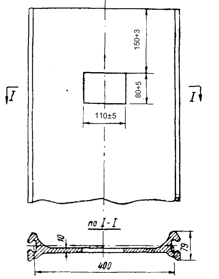
In all cases, a mandatory requirement is the alignment of the upper edge of the hole with a file. Otherwise, when the pile is driven, the irregularities remaining after gas cutting are quickly crushed and the rigidity of the connection between the pile and the vibrator is broken.
Sheet piling is one of the types of hidden work. For paint control, each sheet pile is marked. Above the divisions applied after 1 m, numbers are inscribed with a progressive total, counting from the lower end of the pile. After immersion, the number (according to the log) and the total length of the pile are indicated at the top of the pile.
To achieve a good quality of work, when driving a sheet pile with vibratory drivers, as well as when driving with hammers, guide devices are used. Their purpose is to facilitate the work process and ensure the compliance of the sheet piling structure and its elements with the provision provided for by the project.
Guiding devices for the construction of sheet pile walls with vibratory drivers do not differ structurally from those used when driving with hammers. The design of the guides must meet the following basic requirements: sufficient strength and rigidity, ease of manufacture, ease of assembly and dismantling during work. The design should not allow jamming of sheet piles between the guide elements.
When building cellular structures, special templates are used as guides for sheet piles. Let us consider some of the most typical types of templates used in hydraulic engineering.
On the site of the Gorkovskaya and Kakhovskaya HPPs, one could see cylindrical templates – a through structure welded from rolled profiles, the outer outline of which corresponded to the shape and size of the sheet pile cells. At Gorkovgesstroy, the height of the templates was almost equal to the height of the sheet piling cells above the ground. At the construction of the Kakhovskaya HPP, low templates were made (Figure 75.) Two templates were installed in each cell – one on top of the other. The templates served at the same time as scaffolding, from which the sheet piles were loaded into the previously loaded lock and the vibratory driver was released.

In the initial period of the construction of the longitudinal cellular cofferdam of the pit fencing and the spillway dam of the Stalingrad hydroelectric power station, the so-called sector templates were used (Figure 76.) The design of such a template is a light spatial truss that can rotate around a small pile driven into the ground in the center of the cylindrical cell being erected. Along the contour of the cell, a bent channel is laid on the ground, which serves as a rail for the support rollers of the template.

During the construction of sheet piling cells at the construction of the Kuibyshev HPP, permanent templates were arranged, bent along the contour of the cell, two-tier guides, fixed to sheet piles driven into the ground.
Templates of the original design were used in the construction of the Kairak-Kum hydroelectric power station. Along the outer contour of the welded cylindrical structure, sections of sheet piles 3.8 m long were located, they were interconnected in locks, forming the contour of the cell. Only half of all the sheet piles located along the contour of the template were attached to the frame with pins through one half of all the tongues, the rest were freely inserted into the locks.
The sheet piles were driven into the cell in the following sequence: first, the first sheet pile was installed and driven in the place of the fixed guide section taken out; then, in places of fixed segments along the entire circumference of the template, sheet piles were worked through one. Subsequently, the remaining free sections of the sheet pile were sequentially removed, instead of which normal sheet piles were sunk. In this way, it was possible to easily close the cells without the help of wedge or other shaped sheet piles. After all the sheet piles were driven, the template frame cells were lifted by a crane and moved to the site of the next cell.
It should be noted that the use of complex templates when vibrating sheet piles is not always justified. As the experience of Stalingradgidrostroy shows, sheet piles can be driven into temporary cellular structures using simple templates that mark the contour of the cell on the ground.
When a metal sheet pile is immersed not to its full depth, but in accordance with the project, part of its length (to a height of more than 3-3.5 m) remains above the daytime surface of the soil, then it is advisable to use T-37 type mine hoists to perform work at the level of the top of the sheet pile structure. [33]. When the height of the free length of the submerged sheet pile is low, light portable ladders can be used.
The whole cycle of works on vibratory immersion of a metal sheet pile with the help of jib cranes consists of the following operations:
- laying the tongue with its upper end on a stand in a position convenient for fastening with a vibratory driver:
- refueling the head of the vibratory driver on the sheet pile prepared for immersion and fixing the latter in the head;
- lifting a vibratory driver with a sheet pile and carrying them to the place of immersion:
- driving a previously loaded sheet pile into the lock, lowering to the level of the guides, driving into the guides and lowering to the ground level;
- immersion of the pile into the ground up to the design mark;
- releasing the head of the vibratory hammer from the loaded pile;
- carrying the vibratory driver to the stands to grip the next sheet pile.
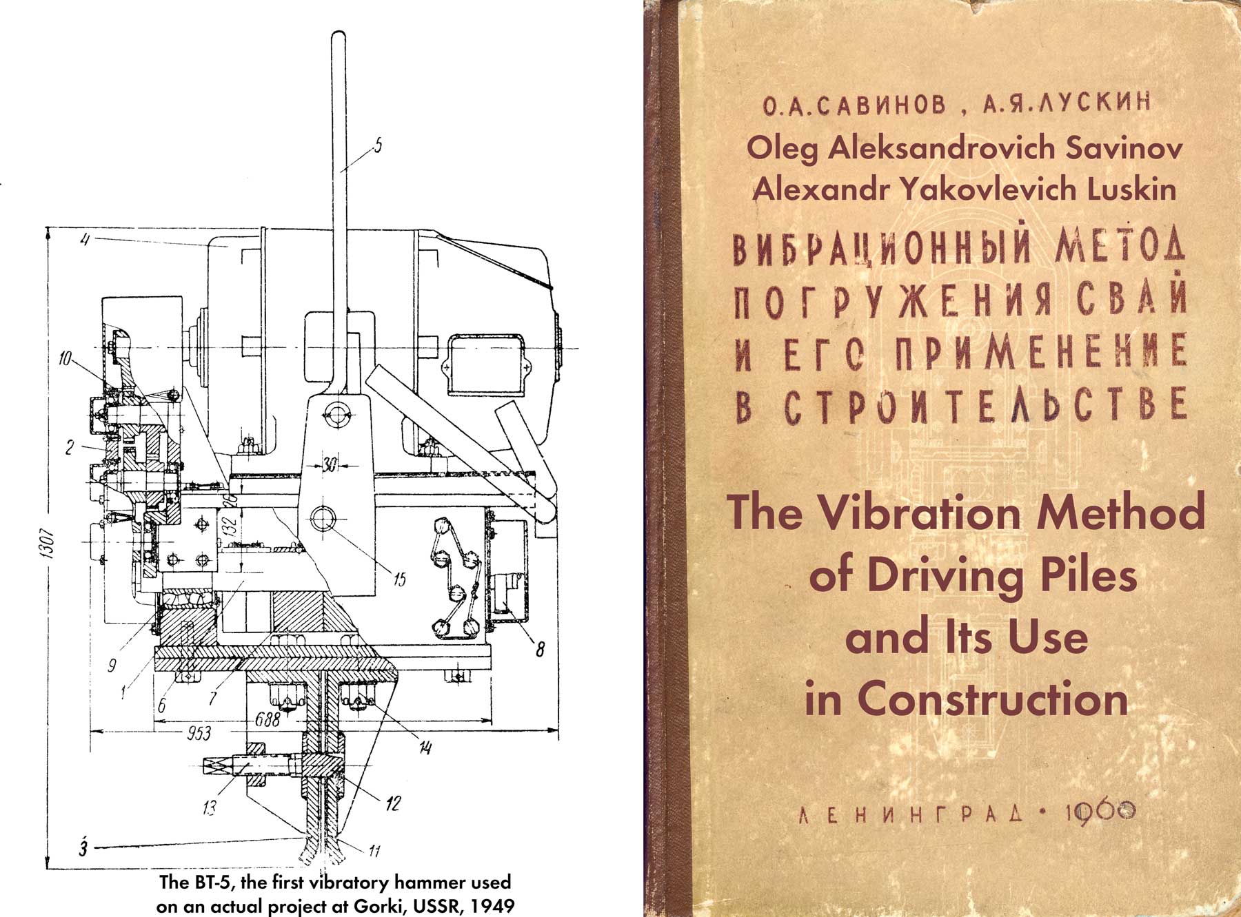
For the first time, a vibratory driver with the help of a clamping wedge was fastened to a sheet pile (with the latter in a horizontal position) at the ground level at Gorkovgesstroy. In this case, vibratory hammers of the BT-5 type were used [32]. Initially, the vibratory pile driver was installed by a crane on the deck. Rotating on special trunnions, it was transferred here to a horizontal position. Then, a sheet pile weighing about 1 ton was dragged with the help of a special roller device (roller table) and refueled into the throat of the cap, the wedge of which was inserted into the hole cut in the sheet pile with the help of a screw. In this way, a rigid fastening of the vibrodriver with the pile was achieved. Subsequently, at the construction of the Gorkovskaya and Kakhovskaya hydroelectric power stations, they began to use the method of capturing the sheet pile, without resorting to the device of the stand.
With the method under consideration, it is not the sheet pile that is inserted into the mouth of the cap, but the vibratory pile driver is pushed onto the pile laid with its upper end on the stand. Initially, the vibratory driver was brought by a crane to a sheet pile laid on a stand and a shortened (by 20-30 mm) cheek was installed on its edge, with further descent of the hook, it leaned and advanced on the pile head. This method was soon abandoned and the vibratory driver began to be placed in a horizontal position on the lining of the sleepers. The crane hook was released from the suspension of the vibratory driver, and with the help of special cables with grippers, the sheet pile was lifted flat and wound into the throat of the head. With this method, a lot of time was spent on removing and putting on the suspension of the vibratory driver on the crane hook.
At Stalingradgidrostroy, during the development of the first samples of vibratory pile drivers, such as VPP-2, the crane operator V. G. Borisov for the first time applied a new sheet pile capture technique [25]. For this purpose, the crane boom was equipped with another cable, fixed at one end to an additional winch drum. There was a small hook at the other end. The sheet pile with its upper end was laid by a crane on a stand. The vibratory hammer suspended on a hook was brought up to the pile. At the signal of the crane operator, the worker threaded an additional hook into the hole in the lower part of the cap. Pulling the cable, the crane operator moved the vibratory pile driver to a horizontal position. With the help of the main and additional cables, he gave the vibratory driver a position in which the machine easily moved over the pile head.
The need for an additional cable soon disappeared, since on the VPP-2 vibratory driver the axis of the suspension hinges was placed close to the line passing through the center of gravity of the entire machine, which facilitated and accelerated the operation of capturing the sheet pile, since the translation of the vibratory driver into a horizontal position and sliding it on a pile was easily carried out by the efforts of one or two workers. Such a technique can be recommended for widespread use.
The supports on which the piles are laid should be installed in places convenient for gripping, lifting and carrying the pile fastened to the vibratory driver, and for immersion without additional crane movements. Sheet piles are placed on a stand by a crane without removing the vibratory driver from the hook. To do this, you should have a special sling, which is temporarily fastened to the head of the vibratory driver and, after laying the piles, is removed from the head.
During the operation of capturing a sheet pile, it is important that the crane operator, at the signal of the driver, by moving the boom and the crane hook, facilitate the sliding of the head onto the pile prepared for immersion. When the end of the pile rests against the slab, by rotating the screw, the wedge is inserted into the hole previously cut in the pile head. With the effort of two workers, using a special key, the screw is screwed in to failure (Figure 77.) When working with caps that also have a lower spacer screw, the latter is screwed in with little effort, and both screws are cottered together with wire.
The bottom screw is designed to prevent horizontal movement of the vibrator on the pile. Therefore, do not overtighten it, as this causes overstressing in the welded seams of the cap and may lead to its breakage. The tightening of the wedge and expansion screw should ensure that the pile is firmly attached to the vibratory driver for the entire time of immersion.
In case of a loose connection, which is determined by the characteristic sound when the cap hits the pile, it is necessary to tighten the wedge, increase control over cutting a hole in the sheet pile and filing the upper edge of the hole, as well as fastening the sheet pile with a vibratory driver. For an additional tightening of the wedge, the pile immersion is stopped at such a height that a worker from the ladder or platform of the mine lift can perform this operation.
Before lifting the vibratory driver with a fastened pile, two ends of a hemp rope 12-15 m long are tied to its lower end.
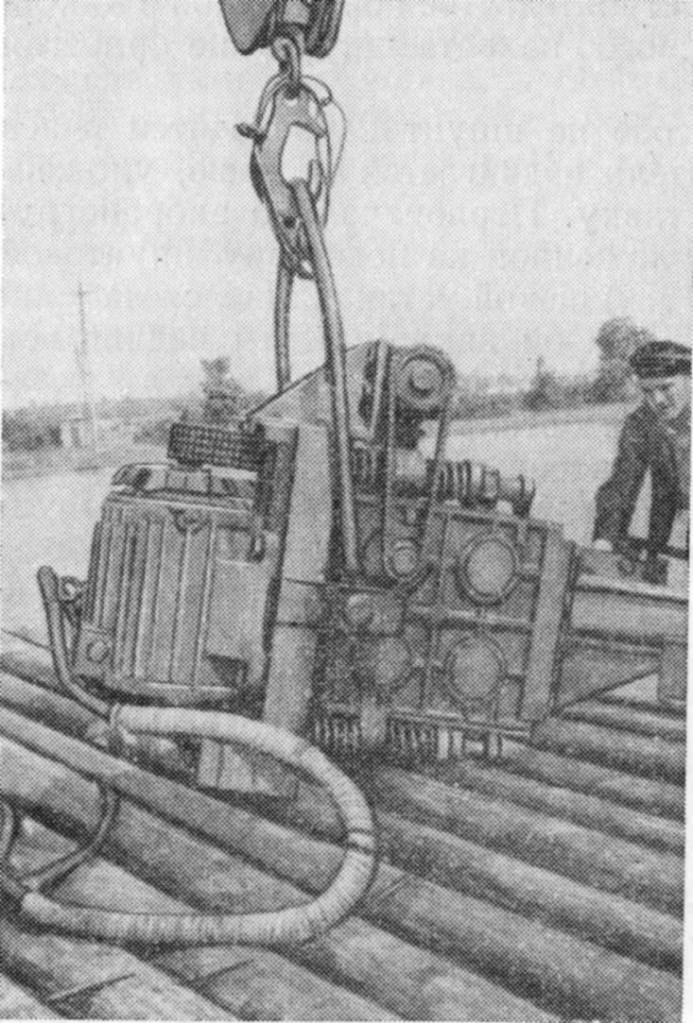
At the signal of the driver, the crane operator lifts the vibratory driver with the pile (Figure 78) and, by turning the boom, transfers it to the place of immersion. At this time, two workers with the help of ropes keep the lower end of the pile from swinging and hitting the piles of sheet piles, the finished part of the structure and other nearby objects. With the help of the same ropes, the pile hanging on the hook is unfolded so that it can be brought into the lock of the previously loaded pile. This operation is carried out after adjusting the position of the hook, in which the connected lock of the hanging pile must be exactly above the free lock of the previously loaded pile.

The pile is brought into the lock by one worker (Figure 79.) After aligning the pile for winding, the crane operator, on a signal from the locker, smoothly lowers it to the level of the guides, then, after refueling into the guides, to a level 20-30 cm from the ground. In this position, the plumbness is checked and the correct location in the guides, and, if necessary, an insert is installed that presses the pile to the guide devices.

It happens that the pile brought into the castle does not slide on the above-ground part of the castle, which was previously loaded. If a vibrodriver of the VPP type is used, then it is turned on for 1-2 seconds. In this case, the pile easily slips down. When working with V-104 and V-108 vibrators, it is impossible to turn on the weight of the machine in order to avoid swinging of the crane boom. Slippage of the immersed pile in the interlock of the immersed pile is ensured by the swaying of the pile in the horizontal direction.
Driving a sheet pile into the ground is done in a variety of ways, depending on the vibratory driver system. When using vibratory hammers of the VPP type, at the signal of the blocker, the crane operator turns on the hitch of the vibratory hammer and, smoothly lowering the crane hook, starts immersing. The speed of descent of the hook should be such that during almost the entire time of immersion the vibratory driver with the pile hangs on the hook (fig. 80.) Only the last 2-3 m of the pile can freely, without braking, sink into the ground.

A decrease in the sinking speed is necessary to achieve a strictly vertical position of the piles in the ground, it should be minimal and completely depends on the experience of the crane operator and the state of the braking devices on the crane winch. As experience shows, compliance with the specified requirement of homogeneous soils completely eliminates the fan and other deviations of the sheet pile. Exceptions may occur if there are obstacles in the ground that can deflect the lower end of the pile being driven.
When the sheet pile is immersed by the B-104 and B-108 vibratory drivers, after alignment, the pile is lowered to the ground and the crane lifting cable is weakened so that the vibrations are not transmitted to the boom. When the cable is loosened, the sheet pile plunges into the ground under the action of its own weight and the weight of the vibrator and inevitably leaves the vertical position due to the fact that the center of gravity is higher than the fulcrum, and sheet piles of the ShP and ShK types, which have low rigidity, also bend. To prevent tilting and bending of the sheet pile when it was driven into the ground by vibratory drivers BT-5 and V-104. At some construction sites, braces were used, fixed to the vibratory driver and held by workers. When sheet piles are driven into soils with hard layers of small thickness or inclusions in the form of formwork residues, sleepers and similar vibratory drivers of the VPP type, overcoming these obstacles is achieved by the following method, which accelerates the sinking process.
With a sharp decrease in the speed of the pile sinking, the crane operator smoothly turns on the winch of the lifting cable and, with the minimum possible speed, proceeds to extract the pile from the ground. Having raised it by 0.8-1 m, he presses the brake pedal, releasing the lifting cable, the pile, sinking at the highest speed, enters a solid layer of soil, and when the reception is repeated, it breaks through it. There are cases when in this way it was possible to overcome clay and gravel layers up to 1.5 — 2 m thick, to cut the sleepers and logs that were in the ground.
The digger is obliged to systematically check the correct position of the piles being driven, to make control measurements. This is of particular importance for the first 3-4 piles. Control measurements with a plumb line are made after driving each of their stages of piles, since errors during subsequent diving can lead to the inclination of previously driven piles. If the results of measurements are unsatisfactory, the piles should be straightened or removed and loaded again. In the future, control measurements are recommended to be repeated after immersion of 10-12 piles.
To eliminate fanning or other deviations, the following measures must be taken:
- repeat the operation of immersion and extraction of the extreme pile to a small height several times;
- pull the top of the sheet piling row with a tractor or a lebelkamp specially installed for this purpose:
- load the wedge-shaped pile.
Multiple immersion-extraction of the extreme pile can be used when working with vibratory drivers of the VPP type in water-saturated sandy and plastic clay soils. In sandy soils of natural moisture, drained, for example, by dewatering, this technique is not recommended, since the soil is strongly compacted, which makes further immersion difficult. The specified reception is performed as follows.
The next pile is immersed to 0.6-0.8 m of the design depth, then slowly removed to a distance of 0.5-0.7 m while pulling the crane hook in the direction opposite to the pile slope. After that, it is again immersed by 1-1.5 m, also with a brace of the top of the sheet pile. The operation is repeated several times until the sheet pile is completely straightened and reaches the design depth. If this technique does not give the desired results, they resort to pulling the top of the submerged sheet piling with a tractor, which is especially convenient when erecting cellular or other sheet piling structures that are curved in terms of plan.
When erecting straight sheet pile walls and rows, one or two manual winches with a load capacity of 3-5 tons each are installed to pull the top of the sheet pile.
The cable from the tractor or winch is securely fixed in the hole of the extreme pile. The cable should be tensioned when the next pile reaches about half the immersion depth, and the cable must necessarily be tensioned with simultaneous vibration of the next pile. This condition is not always met: the cable from the winch is pulled until the next pile is immersed. At the same time, the effectiveness of preventing rolling deviations is significantly reduced.
To compensate for true deviations, wedge-shaped piles are sometimes used, which are driven as usual. Their number and wedge shape should not exceed the norms established for work with the use of percussion projectiles.
When erecting structures from metal sheet piles, a critical operation is the closing of sheet pile cells and rows. As experience shows, this operation does not cause any particular difficulties and requires little effort. If good quality of piling is not ensured, the closing of cells and rows turns into a laborious and time-consuming operation.
The sequence of driving sheet piles into cells should be established in such a way that the closing points are located in cylindrical cells – on the internal elements of the structure contour, and in gabion-type cells – on one of the outer contours.
In the case when the templates used in the construction of the Kairak-Kum HPP are not used, it is recommended to close the cells in the following way. (Figure 81.)
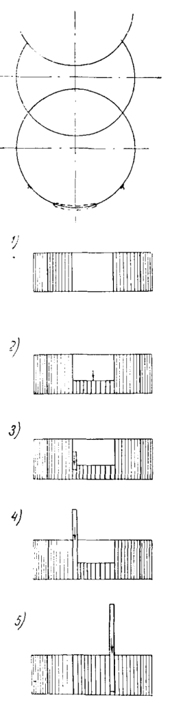
installation of tongue pieces, 3&4) consecutive replacement of pieces of sheet pile,
5) closing the cell and driving the last sheet pile
When 10-12 piles remain to be loaded before closing the cell, the correct position of the extreme piles is carefully checked. if necessary, the row is straightened or a wedge-shaped pile is immersed. Then, cuts of the same sheet pile 0.5-0.8 m long are inserted into the gap between the extreme submerged piles. They are inserted into the locks of the extreme piles and are interconnected by locks. The last cut is simultaneously inserted into the lock of the submerged pile and into the lock of the adjacent cut. If the distance between them does not match, a chain of 10-12 sheet pile cuts is removed or approaches the design contour of the cell until the required distance is formed for winding the last cut. Next, the cuttings are sequentially removed and replaced with sheet piles.
Before sinking, each pile is driven into the lock of the previously plunged pile and then into the lock of the neighboring sheet pile. Boards 50–60 mm thick and 0.5 m long are successively placed under each cut to prevent the cuttings from being pulled into the ground.
When immersed, care is taken to ensure that even gaps in the locks are maintained in the remaining sheet pile chain, that is, that there is no excessive stretching or compression of the chain. With strict observance of this requirement, the last sheet pile will easily sink, being brought into the locks of neighboring piles.
In cases where this cannot be done, before removing the last cut, it is necessary to clarify the distance between the free locks of the outermost piles by driving thin steel wedges from the end of the piles into the gaps between replacements.
In construction practice, it is often necessary to connect separate sections of sheet pile walls, for example, when several cranes are working with vibratory pile drivers on the construction of one long wall, with a complex configuration of the structure, etc.
The mating sections of sheet piles are connected using welded sheet piles. When a distance approximately equal to the width of three piles remains between the connected sections of the wall, it is measured, as well as the slopes of the outermost piles, to designate a special pile. A special pile is made of such dimensions that after it is immersed, a gap remains between the connected sections of the wall, corresponding to the width of two normal piles.
First, a special pile is immersed, then the first normal pile is driven into its free lock, and finally, next to it, a normal pile closes into both locks.
The original design of a special closing sheet pile was proposed by I. M. Kosoy (Riga Department of the Baltspetsgidrostroy trust.) Its width and the angle between the axes of the interlocks can change during driving, adapting to the position of the interlocks of the extreme piles of the mating sections of the structure. The mobility of the interlocks is ensured by the fact that the elements of the pile are connected on bolts, the holes for which are made in the form of grooves, with a length set depending on the angle between the axes of the locks of the mating sheet piles. Such closing piles can only be recommended for temporary structures and in cases where water filtration through slots in the shaped pile is acceptable.
Consider the main features of the combined method of sheet piling. The application of this method depends on the specific conditions: the geological structure of the construction site, the sheet pile profile, the availability of equipment, electricity, etc. It is advisable to use it in cases where rigid profile piles can be driven by vibration to about half the design depth along the entire length of the structure, moreover, the time of immersion of each pile in sandy soils is 2-3 minutes and in clayey 5-8 min. This requirement is due to the following circumstances.
When the pile is vibrated, sandy soils in the immediate vicinity of the pile are compacted. The degree of compaction is greater, the longer the vibration time. With compacted soil, fan-shaped deviations are inevitable, which are completely unacceptable in a sheet piling row, previously assembled and submerged to an incomplete depth.
Based on this, it is necessary to assign the depth of immersion of the sheet pile in such a way that the immersion of each pile throughout the entire length of the structure or over a significant length of it takes no more time than indicated above. When determining the preliminary depth of immersion, it is necessary to take into account other circumstances: the height of the crane hook, the availability of equipment for lifting the worker to the level of the sheet pile wall, where the sheet pile is driven into the lock before the pile is immersed and the head is released from the pile after it is immersed.
Using the combined method, sometimes in order to speed up the work, they strive to immerse the piles by vibration to the maximum possible depth. Experience shows that this goal is not always achieved. On the contrary, excessive compaction of the soil from prolonged vibration, the accumulation of fan deviations create serious difficulties when finishing with hammers, which lead to significant deformations of sheet piles and lengthen the time of work.
Finishing sheet piles with steam-air hammers is usually carried out using pile pile drivers or cranes with suspended booms that serve as guides for the hammer.
Noteworthy is the method of scoring the sheet piling with hammers, proposed by M.A. Aleksandrov and used in the construction of the Kuibyshev hydroelectric power station. Here, a sheet pile wall is used as a guide. For this purpose, a slide 3 made of two channels is attached to the hammer 1 (Fig. 82) with the help of clamps 2. The hammer is installed on two extreme sheet piles of the wall, typed by a vibratory driver. Initially, the crane supports the hammer while driving the first 1.5-2 m. When the sled securely covers the lock of the adjacent sheet pile, the crane is released, as the hammer is held by the neighboring, previously submerged pile.

With this method of sheet pile finishing, one crane can serve two or three hammers.
When finishing a sheet pile with heavy steam-air hammers of the SM-9 and S-231 types, strong deformations of the top of the sheet piles occur. A hole cut in the head of each sheet pile to pre-set the wall and drive it to partial depth with vibrators significantly weakens the top of the sheet pile. In this regard, it is necessary to reinforce the pile heads by welding overlays of thick sheet steel, which somewhat reduce deformations, but do not completely eliminate them.
Due to the formation of significant deformations, it is not recommended to use metal sheet piles of flexible profiles (type ShP and ShK) in such soil conditions, where it will inevitably be necessary to finish with steam-air hammers. It is also not recommended to use composite, welded from two parts, sheet piles. When finishing, welded joints, even well-reinforced with overlays, are often destroyed.


One thought on “Production of Works for Immersion of Metal Sheet Piles Using Jib Cranes”