
For the rest of the book, click here.
The scheme of a pile vibratory driver with a sprung load provides for the implementation of a narrow load in the form of additional elements that are laid on the sprung part and move when immersed together with the pile. This method has well-known advantages, the most important of which is the combination of the vibrator and additional weights into one compact unit, which makes it possible to drive piles from pile drivers or load-lifting cranes without separate loading devices and devices. Obviously, this type of vibrator will be the best for driving elements with a relatively small cross-sectional area (practically up to 2000 cm2), since in this case it is not necessary to give large surcharges. If it is necessary to drive piles of large cross-section into relatively dense soils, it may be necessary to load such a weight at which the installation of a vibratory driver and its use becomes difficult or practically stops.
A way out of the situation is provided by the proposal made by A. G. Davidson, O. A. Savinov and A. Ya. Luskin to use part of the weight of the pile driver as a load when driving piles, ensuring that this weight is included in the work through a special mechanism.*
*Authors Certificate No. 100438 with priority April 10, 1951.
Let us explain this idea with diagrams. Figure 51 shows one of the options for a device with the above features. As a carrier, the use of a crawler-mounted excavator crane is envisaged. In addition to it, the following are used: a special pile boom 1 (Figure 51a), a spacer 2, replaceable drums and a safety clutch to the main winch 3, which provide the necessary speed for sinking or extracting piles, and an additional winch for auxiliary operations. Vibratory driver 4 in this case does not differ significantly from that shown in Figure 35; traction cables are attached to its sprung part. The rope reeving scheme is shown in Figure 51b.*
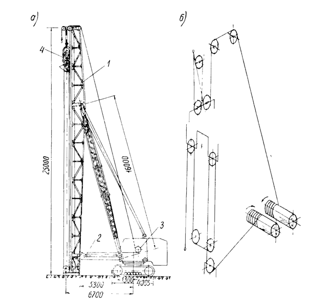
*Instead of a vibratory driver, an impact-vibration hammer can also be used here (see Section 10.)
Springs (spring shock absorber) must provide complete isolation of the entire impact device from vibrations. The fulfillment of this last requirement presents no particular difficulty.
The units built according to the indicated principle of vibratory pile indentation can be used for many types of pile work (installation of vibrated concrete piles and sandy pile-drains, immersion of pile foundations of contact network supports of electrified railway lines, piles under power transmission line supports, etc..)
Pile driving during the construction of high-voltage power lines is carried out, in particular, by units operating on the principle of static pile driving. Such a unit is a tractor of the S-80 type, equipped with a vertical boom (farm), a special winch and a chain hoist. Part of the tractor weight is transferred to the pile, which is installed by the unit in a vertical position, under the action of which the pile is pressed into the ground. Often the weight of one tractor (with additional equipment) is not enough to drive piles with a section of 30 x 30 cm even in relatively soft soils. Therefore, it is necessary either to predrill a leader hole for each pile, the diameter of which is somewhat smaller than the side of the pile section, or to use two tractors in one unit – a worker and an additional load.
According to the considered principle, units for static pressing of piles of the ABC-35 and ABC-48 types, were developed by the Leningrad branch of the Institute Orgenergostroy, operate. The first of them, built on the basis of the S-80 type tractor, can create the greatest crushing pressure equal to 35 tons. The second, consisting of two such tractors, can transfer a vertical force of up to 48 tons to the pile.
Production experience has shown that the use of units operating according to this principle is effective only in clay soils with preliminary soaking of the well. In sandy soils, their use is practically excluded.
The use of vibratory pile driving makes it possible to create more efficient self-propelled units that can be successfully used in all types of soft soils. The arrangement of leader holes will apparently be required only for the most dense and hard clay soils.
Considering these circumstances, the Leningrad branch of the Institute Orgenergostroy, in creative collaboration with VNIIGS, developed two modifications of vibration-pressing units of the types VPS-20/11 and VPS-32/19.* The technical characteristics of the units are given in Table. 17.
| Specifications | VBPS 20/11 | VBPS 32/19 |
| Dynamic Force, tons | 20 | 32 |
| Maximum Downcrowding Force, tons | 11 | 19 |
| Eccentric Moment, kg-cm | 3500 | 6000 |
| Vibration Frequency, RPM | 700-900 | 650-800 |
| Tractor Engine Power, HP | 100 | 140 |
| Generator Power, kW | 60 | 100 |
| Electric Motor Power, kW | 40 | 75 |
| Winch Motor Power, kW | 7 | 14 |
| Total Unit Weight, tons | 23 | 30 |
| Pressure on the Ground Under the Tracks, kg/cm2 | 0.70 | 0.58 |
* E. S. Feld, G. A. Yashkul, Yu. I. Smilovitsky, E. S. Malkov, G. E. Mett and others took part in the design.
The first of these units is intended for buckling reinforced concrete piles with a cross section of 30 x 30 cm, up to 6 m long, and the second – for piles with a cross section of 40 x 40 cm, up to 7 m long.
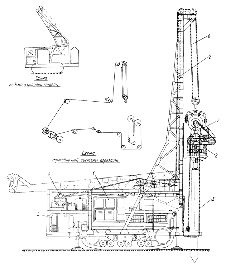
The units have the following device (Figure 52.) A pile boom 2 is fixed to the tractor 1 using a hinged frame, which can rotate when the unit is put into the transport position around a hinge arranged at the height of the top of the tractor cab. An electric current generator 3 is installed on the frame, which is driven from the tractor power take-off. Above the generator there is a double-drum winch 4, with the help of which, and by means of chain hoists 5 and 6, the vibratory driver 7 and the pile are lifted, and the pile-loading (pressing) force is transmitted. This force is transmitted to the vibrator with the pile through the system of springs 8 included in the design of the vibrator.

Rigid connection of the pile with the virodriver is carried out by the following device.
To the head of each pile, with the help of threaded studs protruding from its body*, a steel hollow conical cap is fixed, having an eye for attaching to the end of a steel rope. This rope is fixed in the lower part of the boom, thrown over the block, which is in the suspension of the vibrator, and passes inside the head along its longitudinal axis.
*All piles are supplied with threaded studs for subsequent fastening of line supports.
The immersion of piles by aggregates occurs as follows.
When the vibratory driver is in the lower position, the steel rope of the head is fixed on the cap of the lying pile, prepared for immersion. Then the operator begins to raise the vibratory pile driver. At the same time, the pile rises rapidly, as the distance between the headband and the cap decreases. At a certain height, the pile cap will enter the opening of the vibrator cap. After that, the pile is lowered to the ground and the vibrator is turned on. Initially, the sinking occurs under the action of its own weight. Then the winch is turned on for further sinking.
Upon reaching the design level of pile immersion, the vibratory driver and the winch are stopped, with the help of a special wedge, the head is released from the pile cap and the vibratory driver is raised to a small height, the edge is released from the cap of the submerged pile and moved to the place of immersion of the next pile.
In the event that a pile with its tip meets an insurmountable obstacle in the ground in the form of a large stone or a dense layer, a winch and its drive are provided in the form of an electric relay, which completely excludes the possibility of overloading the unit.


One thought on “Vibratory Downcrowding Units”