
For the rest of the book, click here.
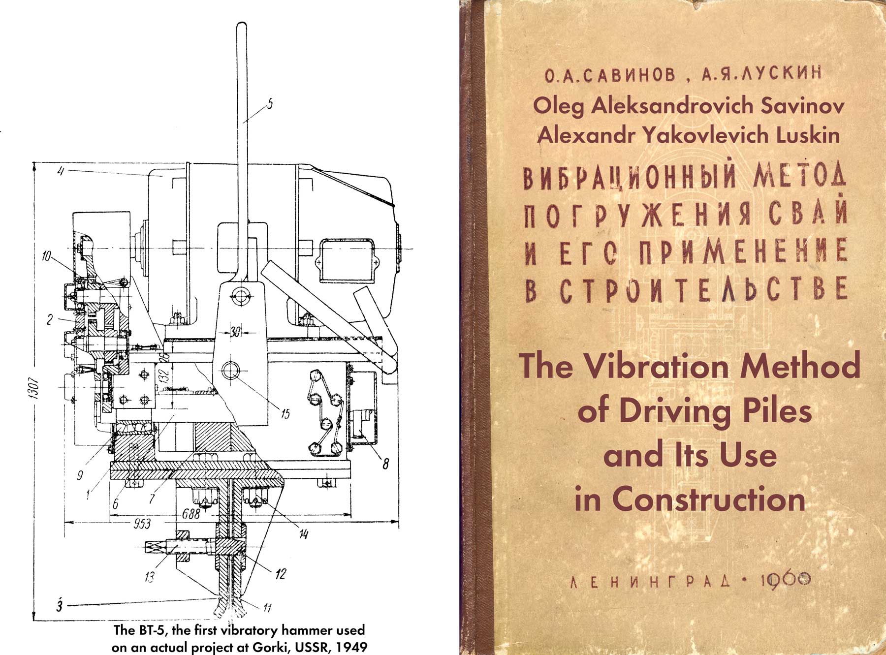
Vibratory hammers with spring load (Figure 35) were proposed by the authors in 1950.* Unlike machines of the simplest type with rigidly connected elements, this vibratory driver consists of two parts – a vibrating one, which includes a vibrator 1 and a cap 2, and a part isolated from vibrations, consisting of loading plates 3 and an electric motor 4. The two parts are connected by a system of springs. The latter must be so elastic that the frequency of natural oscillations of the additional load lies significantly lower than the frequency of rotation of the eccentrics of the vibrator; in this case, the springs begin to play the role of a vibration isolating device. If this condition is met, a change in the mass of the additional load has little effect on the vibration mode of the pile and the vibrator, at the same time, this load makes only very slight vibrations.
*O. A. Savinov, A. Ya. Luskin, Authors certificate N. 94415 with priority dated April 19, 1950
Thus, the proposed scheme of the device of the vibratory driver does not suffer from the disadvantages, which were detailed above, and allows you to independently change the vibration mode and the weight of the vibratory driver.
An approximate solution of the problem of vibrations of a vibrodriver gives a visual representation of the behavior of its parts during operation.
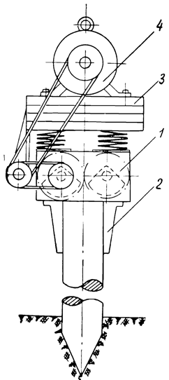
In the first approximation, a pile together with a vibratory driver can be considered as a system with two degrees of freedom (Figure 36.) The following designations are used in the figure:
• 
• 
• 
• 
In order to most clearly present the advantages of a vibratory driver, let us consider the vibrations of the system (Figure 36) in a simplified way, without taking into account the influence of inelastic resistances.*
*This usual simplification, as is known, is quite admissible even in the presence of very significant inelastic resistances in those cases when oscillations of the system outside the resonance region are considered.
With such a formulation of the problem, the expression for the amplitude of forced oscillations of the mass then will have the form:

Where
• 
• 
•

•

•

Since usually 


where 
Let us introduce a new value:

which is the ratio of the amplitude A of the pile oscillations, to which the additional load is attached on the springs, to the amplitude 

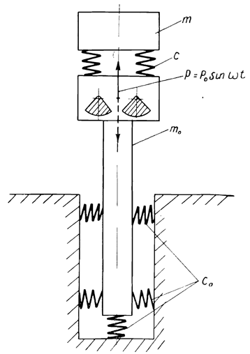
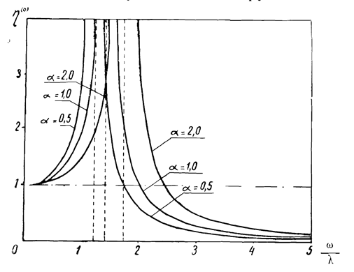
Let us represent the expression (2. 5) in the form of a graph (Figure 37.) When the frequency (


 value versus the
  ratio
ratioThis shows that if an elastic connection is introduced between the vibrator and the additional load, with an appropriate choice of its rigidity, the intensity of the pile vibrations increases with increasing load, and does not decrease, as is the case in the simplest type vibrator. Thus, by attaching an additional load through the springs, we simultaneously increase the weight of the entire system and the intensity of the pile vibrations, which will contribute to the most efficient immersion of the latter.
It follows from the foregoing that it is necessary to strive for the greatest possible reduction in the weight of the vibrator itself, thereby increasing the weight of the additional load to the required limit.
So far, we have considered the oscillations of the pile and the vibrator; let us now find out how the additional load will behave,
The oscillation amplitude of the latter can be represented by the expression:

Assuming that

we have:

 versus ratio
in the event that the additional load and the vibrator were rigidly connected, the amplitude of the load oscillations could be determined by the formula (2.1) The ratio of the oscillation amplitude of the additional load in the presence of a spring connection to the amplitude of the load oscillations when it is rigidly connected to the vibrator will be:

Graph of 

The foregoing confirms the correctness of the proposition that the proposed principle of the device of the vibratory driver provides separate control of the factors on which the effect of pile driving depends – the intensity of vibrations and the plunging pressure. The sprung vibrator has other advantages:
a) the possibility of installing an electric motor on an additional (sprung) load that does not experience vibrations in the process of piling, and the fundamental improvement in engine operating conditions associated with this;
b) the possibility of using electric motors with phase rotors that have the best starting data;
c) no need for a special shock-absorbing device for extracting piles.
To test the validity of the theoretical considerations underlying the design of a sprung-loaded pile vibratory driver, special observations were made on the behavior of piles driven under production conditions. They consisted in measuring the amplitude of vibrations of piles and elements of the vibratory driver at various moments of immersion, control measurements of the frequency of rotation of the vibrator eccentrics, as well as determining the speed of immersion of piles.
The observations showed the following:
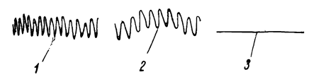
- Attaching additional weights to the sprung part of the vibratory driver does not change the vibration mode of the piles; at the same time, the sprung part does not experience vibrations during the immersion process. To illustrate, here are sections of the vibration recording of two identical wooden piles (28 cm in diameter, 12 M long), submerged at the same vibrator setting (at = 1500 RPM, K = 550 kg-cm), but with different weights of the sprung load (Figure 39.) The change in the weight of the sprung part from 1.4 to 2.9 tons, i.e., more than twice, had practically no effect on the amplitude of the pile vibrations.
- The magnitudes of the pile vibration amplitudes determined by the formulas in cases of using high-frequency vibrators
correspond very closely to those measured in nature.
For example, in the case to which Figure 39, the calculation showed an amplitude value of 4.5 mm, while 4.6 mm was measured in nature.
Thus, the theoretical considerations underlying the design of a sprung-loaded vibrator and the data of field observations are in good agreement.
Based on the diagram above, the authors have developed the designs of several VPP-type vibratory hammers with sprung surcharge VPM with a sprung motor.* These machines have the following common features:
a) each machine consists of two parts – a vibrator and an additional load, interconnected by elastic springs;
b) the selection of the weight of the vibratory driver, necessary to ensure the best effect of immersion, was carried out by increasing or decreasing the weight of the additional load;
c) the weight of the vibrator itself is taken to be minimal;
d) the electric motor is mounted on an additional load, which practically does not experience vibrations during the operation of the vibratory driver.
* M. G. Tseitlin, S. V. Plekhanova and Yu. Melbart.
In connection with the latter feature, some difficulties arose in the process of developing the drive design, the operation of which should not be affected by the mutual displacements of the vibrator and the electric motor. This condition is met by a drive from a two-stage V-belt or chain transmission. Rotation from the electric motor shaft is transmitted to an additional shaft, the supports of which are fixed on an additional load, and from the intermediate shaft – by a horizontal branch to the vibrator drive shaft. With such a drive device, the center-to-center distances practically do not change, while the distance between the vibrator and the electric motor can vary within relatively large limits.
The vibrators of the considered system have been in operation for a long time. The test results and production experience of their application fully confirmed the correctness of the theoretical assumptions underlying the design of vibratory hammers. As it turned out, these machines are quite reliable and easy to use, which makes it possible to recommend them after appropriate refinement for mass production,
The first of the machines built according to the scheme of a vibratory driver with sprung surcharge is the VPP-1 vibratory driver. Its parameters (Table 15) are selected in such a way as to ensure the immersion of pipes and piles weighing up to 2 tons in water-saturated sandy and weak clay soils to a depth of 14-16 m. installation of vibrated concrete piles and sand piles-drains, as well as long – up to 14 m – wooden piles. To immerse the metal inventory pipe, it was provided for its blind fastening with a vibratory driver by means of a flange. For immersion of wooden piles, the design of a special cap was developed. However, during operation, the machine was used to drive piles: tubular metal, closed from below, box-shaped, welded, from Larsen-type sheet piles, and light reinforced concrete. In all cases, depending on local conditions, various types of devices were used to fasten the vibratory driver with the submerged element.
| Specification | VPP-1 | VPP-2 | VPP-4 | VPP-5 | VPP-6 |
| Largest Eccentric Moment, kg-cm | 1000 | 1000 | 550 | 350 | 250 |
| Vibration Frequency, RPM | 1500 | 1500 | 1300-1500 | 1500 | 1500-1200 |
| Dynamic Force, tons | 25 | 25 | 14 | 8.8 | 6.2 |
| Weight of Vibrating Parts, tons | 0.7 | 0.7 | 0.4 | 0.35 | 0.25 |
| Weight of the Main Load, tons | 1.4 | 1.5 | 0.8 | 0.85 | 0.5 |
| Weight of the Additional Load, tons | 2.4 | – | 0.8 | – | – |
| Total Weight of Vibrator With Main Load, tons | 2.1 | 2.2 | 1.2 | 1.2 | 0.75 |
| Total Weight With Additional Load, Tons | 4.5 | – | 2 | – | – |
| Vibration Amplitude Without Piles, mm | 14.3 | 14.3 | 13.8 | 10.0 | 10 |
| Motor Power, kW | 30 | 40 | 28 | 16 | 11 |
| Overall Dimensions in Plan, mm | 1010 x 950 | 1270 x 800 | 1000 x 960 | 1250 x 680 | 830 x 760 |
| Height (without headband,), mm | 1630* | 2250 | 1500* | 1250 | 1380 |
*Without additional load.
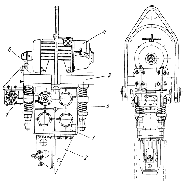
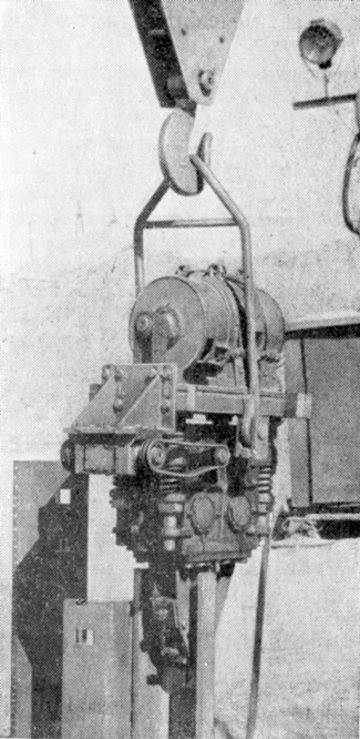
A vibratory driver of the VPP-l type (Figure 40) consists of a vibrator 1, a main loading plate 2, an electric motor 3, a spring device 4, a V-belt transmission 5 and a suspension 6. The vibrator is a welded box, inside which shafts with eccentrics are placed, and gears synchronizing their rotation.
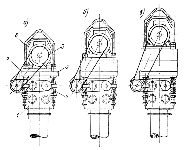
The main loading plate, on which the electric motor is mounted, is connected to the vibrator by means of eight springs, through which guide rods pass, fastened to the loading plate. To the latter, in addition, the brackets of the auxiliary shaft of the V-belt drive and the suspension are attached.
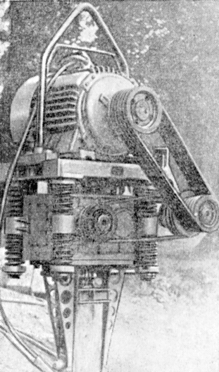
As can be seen from Table. 15, the VPP-1 type vibratory hammer has an additional surcharge consisting of two parts with a total weight of 2.4 m. Depending on the cross-sectional area of the immersed pipes or piles and soil conditions, the vibratory driver can operate without additional loading plates (Figure 40a), with full plates (Figure 40b) or with full weight loading (Figure 40c.)
To install additional loading plates, the electric motor with suspension is separated from the vibrator. These plates are laid on the main loading plate. Then the electric motor and suspension are fixed. At the same time, V-belts of the vertical branch of the transmission are replaced by longer ones, corresponding to the new center distance between the axes of the electric motor shaft and the auxiliary drive shaft.
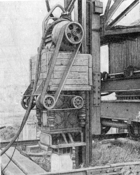
Figure 41 shows a general view of the VPP-1 type vibratory driver with a full additional load.
The VPP-2 vibratory driver (Figure 42) is designed to drive a metal sheet pile weighing up to 1.5 tons into water-saturated sandy soils to a depth of 12-15 m and into weak plastic clay soils to a depth of 10 m. It can also be used to extract metal sheet piles from the ground.
The machine has the same basic parameters as the VPP-1 vibratory pile driver, but differs in the absence of additional surcharge. According to the general layout and design, these machines differ significantly from each other, which is due to the difference in the technology of piling and sheet pile driving.
When driving a pile with a VPP-1 vibratory driver, all operations are usually reduced to raising and lowering the vibratory driver (without turning it into a horizontal position), and the longest elements are usually immersed using guide pile driver arrows.
When immersing a metal sheet pile, as already mentioned, in order to capture sheet piles, it is necessary to turn the vibratory driver into a horizontal position, move your own with it for some distance next to the guide devices and finished parts of the structure. In this regard, the machine must have such a shape and dimensions that would ensure the convenience of performing these auxiliary operations. For this purpose, a different arrangement of the electric motor was adopted, which made it possible to reduce the size of the vibratory driver (in width) and make it more convenient to use.
In addition, the VPP-2 type vibratory driver differs from the first model in the following features: the vibrator is driven by a two-stage chain and bevel gears; the suspension is articulated with a different location of the hinge axes, which are close to the axis passing through the center of gravity of the entire machine, which greatly facilitates the turn of the vibratory driver into a horizontal position: a wedge head is used to quickly and reliably fasten the sheet pile to the vibrator.
The vibrator mechanism (Figure 43) and the suspension device are similar to those used in the VPP-I type vibrator.
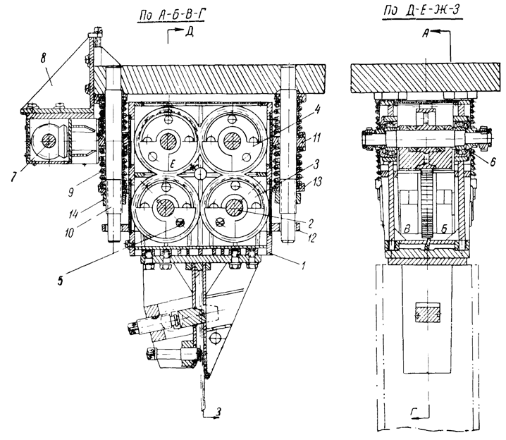
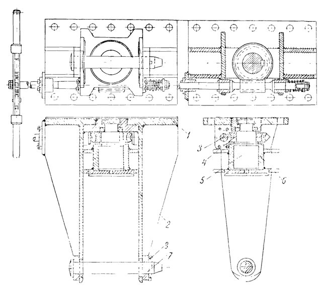
Four shafts 2 with gears 3 and eccentrics 4 are installed in the welded body of the vibrator 1. On each side of the gear, one eccentric is installed, consisting of two parts – movable and fixed. Due to the displacement of the moving part, the magnitude of the moment of eccentrics is regulated.
The fixed parts of the two eccentrics located on different sides of the gear are rigidly fastened with bolts d, and the movable ones are fixed at certain angles with respect to the fixed ones with the help of clamps 6 and spiral springs 7 (Figure 44.)
To transfer the movable part to a new position, the latch is sunk into the body of the deblanc, and the protrusion of the latch comes out of the hole on the gear rim. After turning the movable part to the proper angle, the latch is pushed out by the spring and enters with its protrusion into another hole corresponding to this angle.
The eccentric-bearing shafts 2 protrude onto the walls of the vibrator housing through spherical roller bearings 8. One shaft has protruding ends, on which the driven sprockets of the chain drive are mounted. The transmission of rotation to these sprockets is carried out by two double-row bush-roller chains from the bevel gear shaft 9, parallel to the vibrator shafts. The second roller of the bevel gear, perpendicular to the vibrator shafts and parallel to the motor shaft, is driven from it by a four-row bush-roller chain.
The body of the bevel gear is attached to the loading plate using brackets 10. The bolt holes are the rest, which allows you to adjust the tension of the chains.
The design of the spring device that cushions the load (see Figure 43) consists of eight helical springs 11, through which guide rods 12 are threaded. To stop the springs on the vibrator body, there are four springs 18, and to restrict the freedom of rotation of the vibrator relative to the load plate – guide washers 14. The guide rods are fixed at the top end in the loading plate, and at the bottom they are threaded, which allows adjusting the tension of the springs with the help of plates 15 and nuts 16. For the vibrator to work, it is necessary that the springs are pre-compressed by the described device to approximately half of their full deflection. With this tension of the springs, the axes of the drive shaft of the bevel gear and the driven shaft of the vibrator are approximately on the same horizontal line (with the vibrator in a vertical position.)
The tension of the springs also regulates the position of the rods 12 in the guide washers 14. The correct position of the rods is that which maintains a uniform gap between them and the washers. The rods touching the washers during the operation of the vibrator should not take place.
The cap (Figure 45) is intended for rigid fastening of the vibratory driver with a sheet pile being driven or retrieved. Its design is adopted basically the same as on BT-5 type vibrators. The changes boil down to the following:
- the width of the pharynx between the cheeks of 1 cap is increased to 30 mm. This facilitates the installation of the cap on sheet piles having a wall thickness of 10 to 22 mm;
- a replaceable insert 2 is placed in the upper part of the throat, and a screw 3 is placed in the lower part, which ensure that the tongue wall is pressed against one cheek of the cap. The dimensions of the replaceable liner are set depending on the wall thickness of the sheet pile;
- wedge 4 and screw 5, with the help of which the wedge is inserted into the hole cut in the head of the sheet pile, are located not perpendicular to the pile axis, but at an angle of 80°. This creates the possibility with a small range of motion of the wedge to obtain a reliable fastening of the pile with the head when the distance from the end of the pile to the upper edge of the hole deviates by 3-4 mm in both directions:
- there are guides on the dowels b, along which the wedge moves when driving it into the hole of the pile. This eliminates the possibility of warping the wedge.
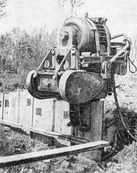
A general view of the VPP-2 type vibrodriver in the working position is shown in Figure 46.
In accordance with the project, squirrel-cage electric motors of the AOP-83-6 type (with increased starting torque) with a power of 40 kW, with a speed of 960 RPM, should be installed on the VPP-2 type vibratory drivers. Such electric motors would easily spin the vibrator with the full moment of eccentrics, allowing short-term overloads up to 60-65 kW. However, it is not always possible to obtain such electric motors. It is impossible to replace them with electric motors of a single series of general purpose type A and AO of the same power, since they are not able to spin the vibrator with an eccentric moment of 1000 kg-cm.
It should be borne in mind that usually the mechanical strength of electric motors, the body and flanges of which are made of thin-walled cast iron, is insufficient for use on vibratory drivers. Therefore, at Stalingradgidrostroy, electric motors were subjected to some reconstruction, which consisted in replacing cast-iron end flanges with steel ones.
The difficulty in the selection of electric motors for VPP-2 vibratory pile drivers was solved differently in different organizations.
Thus, the Gidrospetsfunlamentstroy trust produced more than 100 vibratory pile drivers with crane motors with a capacity of 28 kW of the MTK-52-8 type, with a duty cycle of 25% and 695 RPM. These electric motors are quite satisfactory both in terms of electrical and mechanical properties, but their power is insufficient to work with the full moment of eccentrics. Therefore, they can be recommended only for those conditions when the immersion or extraction of the sheet pile is provided by the moment of eccentrics of the vibratory driver, equal to 700 kg-cm.
Some construction organizations installed electric motors of a different design on vibratory pile drivers of the VPP-2 type. Thus, explosion-proof electric motors with a capacity of 46 kW were used at the construction of the Kakhovka hydroelectric complex, which fully justified themselves. At the construction of the Leningrad metro, vibratory drivers of the VPP-2 type with old-manufactured electric motors with a capacity of 42 kW were used, which also worked quite satisfactorily.
At the construction of the Stalingrad hydroelectric power plant, VPP-2 type vibratory hammers were used for the first time on a mass scale. Extensive research was carried out here [55], as a result of which it was found that vibratory drivers of the VPP-2 type with a 1000 kg-cm debgl. kW with a speed of 960 RPM. The electric motors are mounted on a load plate and require a better matching of the length of the chain drive with the new center distance between the axes of the electric motor and the bevel gear.
At the same construction site, several VPP-2 vibratory hammers were modernized, which consisted in bringing the eccentric moment to 1100 kg-cm and increasing the weight of the loading plate. On some machines, the weight of the surcharge, together with the electric motor, was approximately 2700 kg, and the total weight reached 3400 kg. On these machines, electric motors with a power of 55 kW were installed. On others, the weight of the surcharge was brought up to 3000 kg with a total weight of the machine of about 3800 kg: electric motors were installed with a power of 75 kW.
The BPP-4 type vibratory driver (Figure 47) for driving wooden piles is similar to the VPP-1, but since it was calculated for a maximum disturbing force equal to only 14 tons, then its vibrator 47. The VPP-4 vibrator was made two-shaft (on four main bearings), in contrast to the sprung-loaded vibrators discussed above, in which eccentrics are placed on four shafts to increase the durability of the bearings.
This made it possible to reduce the weight of the VPP-4 vibrator by almost half compared to VPP-l and VPP-2.
The relatively small weight of the vibrator makes the VPP-4 type vibratory driver very sensitive to changes in the weight of the submerged elements.
The use of the full moment of eccentrics when driving light piles leads to an excess of the vibration amplitude over the required value, and, consequently, to a useless overload of the electric motor. Reducing the amplitude by changing the moment of eccentrics in some cases can cause such a significant decrease in the magnitude of the perturbing force that immersion becomes difficult. To eliminate this shortcoming, an additional pulley and V-belts were included in the vibrator kit, allowing the vibrator to be driven up to 1750 RPM. The system for adjusting and fixing the balances to change their moment is similar to that described above for the VPP-2 type vibratory driver.
In VPP-4 vibratory hammers, like VPP-1, the suspension does not have trunions, which excludes the possibility of turning the machine into a horizontal position to fasten it to the pile. For immersion of wooden and light reinforced concrete piles by the indicated vibratory drivers, a new design of the head was proposed, * allowing the pile to be pivotally connected to the vibratory driver when it is in the lower position, and rigidly fastened together after lifting the machine with the pile.
*O. A. Savinov, A. Ya. Luskin, Author’s Certificate No. 93969 with priority dated November 19, 1951
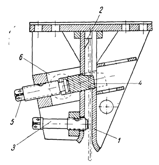
The headband (Figure 48) has the following device. Two rigid necks and 2 are welded to the plate 1, between which in the upper part there is a worm 3 and a worm wheel 4. A jack screw 5 is fastened to the worm wheel, which enters the clamping plate 6 with its screw thread, which closes in the headband with a safety pin 8.
To immerse a pile with a cap of the considered design, its upper part should have two edges narrowing the head to 22 cm, corresponding to the distance between the cheeks of the cap, and a hole with a diameter of 51 mm, located at a distance of 350 mm from the end of the pile.
When the vibratory driver, suspended from the hook of a crane or pile driver, is in the lower position, the pile is driven into the cap. The king pin is inserted so that it passes through the cheeks of the cap and the body of the pile. After that, the vibratory hammer with the hinged pile is raised so that the pile is suspended in the air, and the pressure plate is lowered using a worm gear until it rests against the end of the pile and clamps it to failure. The rotation of the worm is made by a double-sided ratchet wrench, which is controlled from the ground by two ropes attached to its ends.
The use of caps operating according to the described principle for driving wooden and small reinforced concrete piles gave quite satisfactory results.
During the operation of the VPP-4 vibratory driver, design flaws were identified that narrowed the boundaries of the use of vibratory drivers (for example, it was impossible to immerse a metal sheet pile with a machine), as well as reducing its performance: the rigid connection of the suspension with the sub-engine frame and its inconvenient location did not allow the vibratory driver to turn into a horizontal position for fastening with embedded piles: no special caps for driving wooden and metal sheet piles: an inconvenient device for adjusting the belt tension, no devices for controlling the oil level in the vibrator housing, etc.
In 1955, a new version of the VPP-4A vibratory hammer was developed, devoid of these shortcomings. The main parameters are kept the same as in VPP-4 type vibrators. In connection with the replacement of the underframe with a solid plate, only the weight of the main sprung load increased by 300 kg.
The new design provides for an articulated suspension that allows the vibratory driver hanging on the hook to turn into a horizontal position and, therefore, a chain drive instead of a V-belt drive used on VPP-4 type vibratory drivers.
Simultaneously with the improvement of the machine, new designs of caps were developed – for immersion: wooden piles and sheet piles, as well as metal sheet piles.
VPP-5 and VPP-6 sprung vibratory hammers were designed specifically for driving and extracting metal and wooden sheet piles up to 7 m long, used to protect the walls of trenches and pits when laying pipelines for various purposes.
The VPP-5 vibratory hammer (Figure 49) is arranged in the same way as the VPP-2. For convenience, a bevel gear is again used in it, since the axes of the vibrator shafts are not parallel to the axis of the motor shaft. The suspension in this car is articulated, lies in a plane perpendicular to the axis of the electric motor shaft, due to which it has greatly decreased.
In search of the best design solution, simultaneously with the development of the VPP-5 type vibratory driver, a second model was created – VPP-5A, identical in terms of parameters. but arranged according to the scheme of a VPP-4 type vibratory driver, with a suspension located in a plane perpendicular to the axes of the electric motor and vibrator shafts. Tests and production application of VPP-5 and VPP-5A vibratory hammers have shown that the first of them is more convenient in operation and is more productive.
During the operation of the considered models of machines, it turned out that in many cases their power for a short sheet pile turned out to be excessive. Thus, the time of immersion of metal sheet piles to a depth of 5-6 m was 30-40 seconds. Considering this circumstance, as well as the fact that there are not always sources of energy of sufficient power nearby on city highways, VNIIGS, at the suggestion of the Lenvodkanalstroy trust, developed a model of a less powerful vibratory driver of the VPP-6 type.
The layout of this machine differs from all others in that in it (in the absence of a bevel gear) the suspension, the hinges of which are located close to the axis passing through the center of gravity, lies in a plane passing through the axis of the electric motor parallel to the axes of the vibrator shafts.
In addition to the considered group of vibratory pile drivers with sprung surcharge, the authors, with the participation of M. G. Tsentlin, developed designs for two small vibratory pile drivers with sprung motors (VPM-1 and VPM-2 types.) The technical characteristics of these machines are given in Table. 16.
| Specifications | Model of Vibrator | |
| VPM-1 | VPM-2 | |
| Largest Eccentric Moment, kg-cm | 60 | 150 |
| Vibration Frequency, RPM | 1500 | 1500-1800 |
| Largest Dynamic Force, tons | 1.5 | 5.7 |
| Motor Power, kW | 3.7 | 7.0 |
| Weight of Vibrating Parts, kg | 50 | 115 |
| Total Weight, kg | 150 | 330 |
| Dimensions in Plan, mm | 500 x 390 | 630 x 530 |
| Height, mm | 940 | 1375 |
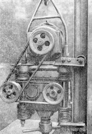
Vibratory hammer type VPM-l (Figure 50) is intended mainly for driving in water-saturated sandy and plastic clay soils with probes with a diameter of up to 89 mm to a depth of 20 m.
In addition, the vibratory hammers can be used to drive and retrieve wooden sheet pile up to 4 m long, piezometric pipes, earth pipes, etc. The operation of the VPM-l type vibratory driver for several years has shown that it is quite suitable for its purpose. At the same time, there was a need for a more powerful vibratory driver of the same purpose, capable, in particular, of immersing probes with a diameter of up to 168 mm to a depth of 25 m.
For these purposes, the design of the VPM-2 vibratory driver was developed, which is approximately twice as powerful as the VPM-1 vibratory driver.


3 thoughts on “Suspended Vibratory Hammers”